Electric vehicle brake control device

a technology for brake control and electric vehicles, applied in brake systems, brake components, transportation and packaging, etc., can solve the problems of shortage of braking force, pressure difference between the pressure of the pressure difference between the wheel cylinder and the master cylinder becomes lower than the expected value, so as to reduce the deceleration of the vehicle

Inactive Publication Date: 2013-09-12
NISSAN MOTOR CO LTD
View PDF0 Cites 14 Cited by
  • Summary
  • Abstract
  • Description
  • Claims
  • Application Information

AI Technical Summary

Benefits of technology

[0009]Accordingly, upon braking operation, due to function of the regenerative cooperative brake control means, the driver-desired deceleration is achieved by the sum of the base hydraulic pressure part and the regenerative part and the insufficient regenerative part is compensated by the pressure increased part produced by the brake fluid pressure actuator. Furthermore, due to function of the differential pressure regulating valve operation control means, when the regenerative cooperative brake control stops the pump motor, the differential pressure control by the differential pressure regulating valve is carried out based on the rotation speed of the pump motor. That is, if, at the time of stopping the pump motor, the control for obtaining the desired pressure difference is kept under running of the pump motor, the pressure difference between the wheel cylinder pressure and the master cylinder pressure becomes lower than the expected value inducing a short...

Problems solved by technology

That is, if, at the time of stopping the pump motor, the control for obtaining the desired pressure difference is kept under running of the pump motor, the pressure difference between ...

Method used


Image

  • Electric vehicle brake control device
  • Electric vehicle brake control device
  • Electric vehicle brake control device

Examples


embodiment-1

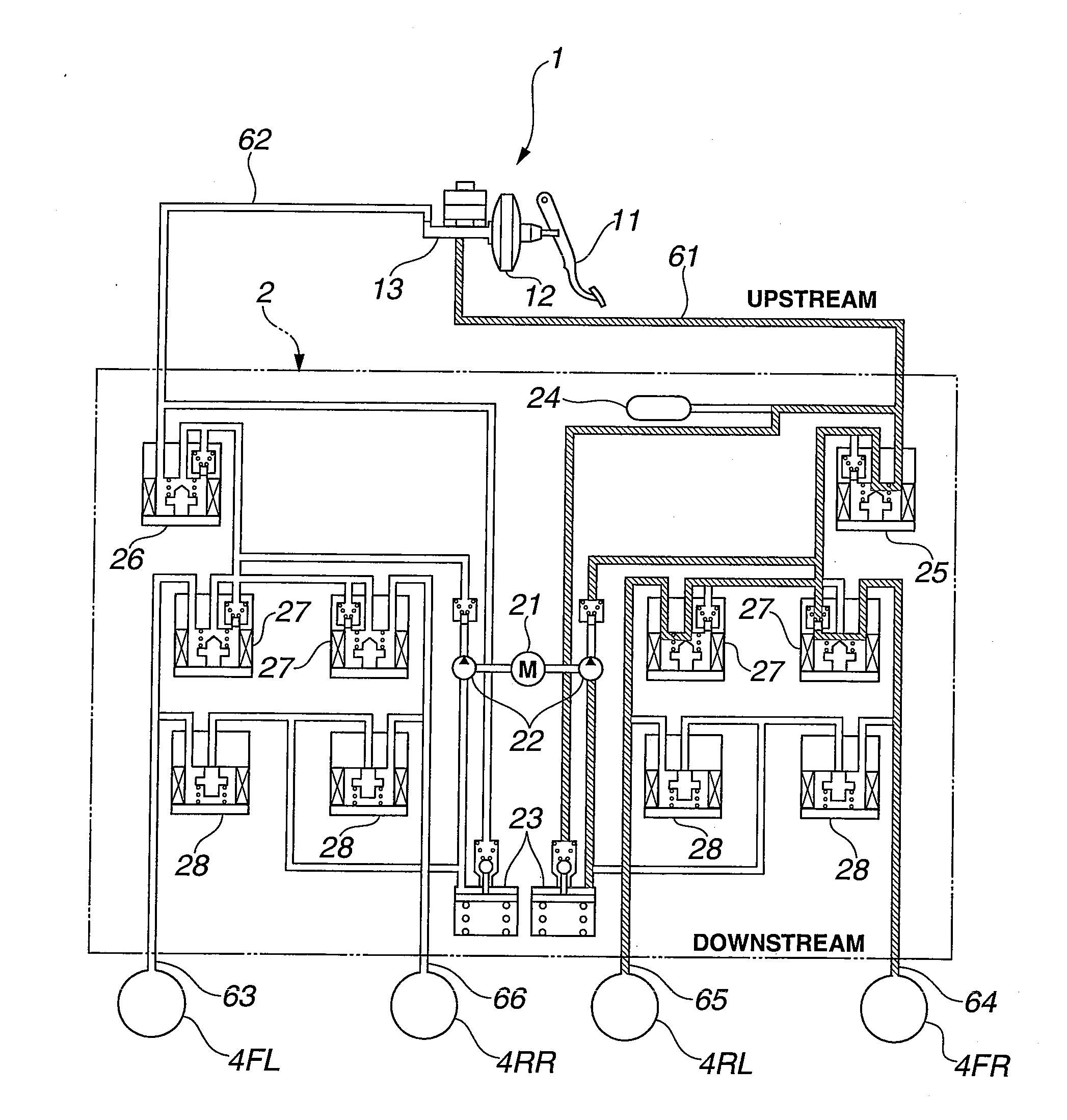
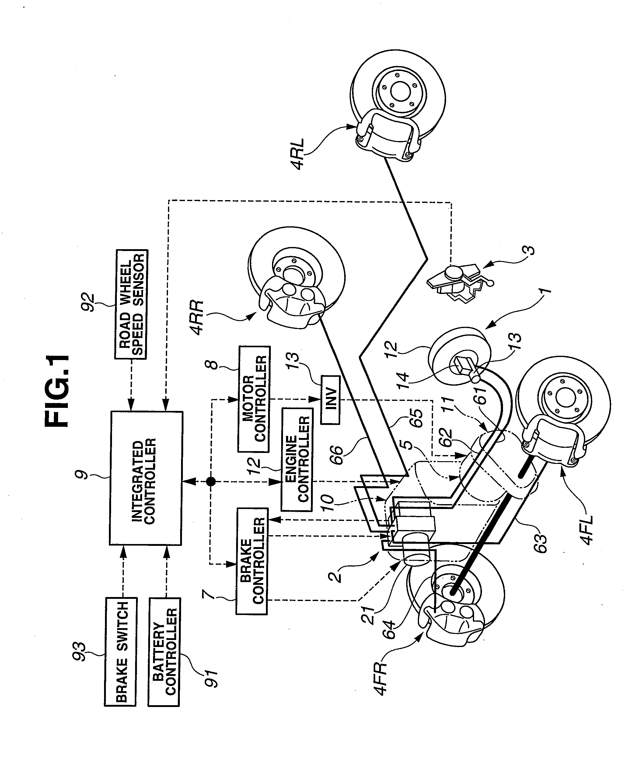
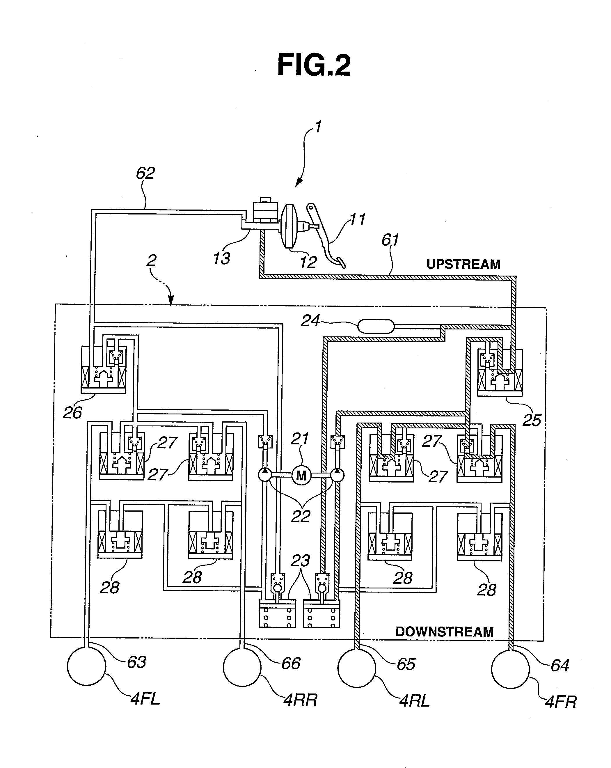
[0022]At first, the description will be directed to a construction. FIG. 1 is a diagram showing a construction of a hybrid vehicle (one example of electric vehicles) of front wheel drive type to which a brake control device of an embodiment-1 of the invention is practically applied. FIG. 2 is a schematic drawing of a brake fluid circuit showing a VDC brake fluid pressure unit (one example of brake fluid pressure actuators) employed in the brake control device. In the following, the construction of the brake system will be described with reference to FIGS. 1 and 2.

[0023]As is shown in FIG. 1, a brake deceleration generating system of the brake control device of the embodiment-1 comprises a brake fluid pressure generating device 1, a VDC brake fluid pressure unit 2 (viz., brake fluid pressure actuator), a stroke sensor 3, a wheel cylinder 4FL for a front-left road wheel (which will be called “front-left wheel cylinder” hereinafter), a wheel cylinder 4FR for a front-right road wheel (w...


PUM


Abstract

A brake control device of an electric vehicle comprises a master cylinder, wheel cylinders, a VDC brake fluid pressure unit, a motor controller and an integrated controller. The motor controller controls a regenerative braking force produced by a vehicle driving electric motor. The integrated controller achieves, upon braking operation, a driver-desired deceleration based on the sum of a base hydraulic pressure part produced by a master cylinder pressure and a regenerative part produced by the regenerative braking force and compensates an insufficient regenerative part with a pressure increased part produced by the VDC brake fluid pressure unit. In addition to this, at the time when the VDC motor is stopped due to the regenerative cooperative brake control, a pressure difference control effected by M/C cut solenoid valves and which are differential pressure regulating valves is carried out based on a motor rotation speed of the VDC motor.

Description

TECHNICAL [0001]The present invention relates to an electric vehicle brake control device that carries out a regenerative cooperative brake control by achieving a deceleration, which is desired by the driver, based on the sum of a base hydraulic pressure part and a regenerative part and compensating an insufficient regenerative part with a pressure increased part of the base hydraulic pressure.BACKGROUND ART[0002]Hitherto, a vehicle brake control device has been proposed in which a regenerative cooperative brake control is carried out by achieving a deceleration, which is desired by a driver, based on the sum of a base hydraulic pressure part and a regenerative part and compensating an insufficient regenerative part with a pressure increased part of the base hydraulic pressure (for example, Patent Document 1).[0003]In this conventional device, by controlling a differential pressure regulating valve installed between a master cylinder and a wheel cylinder and causing a hydraulic pump...

Claims


Application Information

Patent Timeline
IPC IPC(8): B60T13/58
CPCB60T1/10B60T7/042B60T13/586B60T13/662B60Y2300/89B60W10/08B60W10/188B60W30/18127B60W2050/0012B60T2270/604B60T8/4872
Inventor MORISHITA, SHINICHIRO
Owner NISSAN MOTOR CO LTD
Why Eureka
Try Eureka