
CMOS Temperature Sensor with Sensitivity Set by Current-Mirror and Resistor Ratios without Limiting DC Bias

Inactive Publication Date: 2013-09-12
HONG KONG APPLIED SCI & TECH RES INST
View PDF14 Cites 17 Cited by
  • Summary
  • Abstract
  • Description
  • Claims
  • Application Information

AI Technical Summary

Benefits of technology

The invention is about improving temperature sensing circuits in integrated circuits. The technical effect of the invention is to provide a temperature sensor circuit that does not require a special process technology, but instead uses a standard CMOS process. The circuit should also scale the temperature sensitivity using a resistor ratio or current-minor ration, rather than reducing the voltage headroom. Additionally, the circuit should cancel the saturation current term and not require an ideal current source.

Problems solved by technology

However, the tightly packed transistors generate heat, especially at higher operating frequencies.
Hotspots on the chip can cause erratic circuit function or even permanent damage.
However, some temperature monitoring circuits require a more expensive BiCMOS technology rather than standard complementary metal-oxide-semiconductor (CMOS).
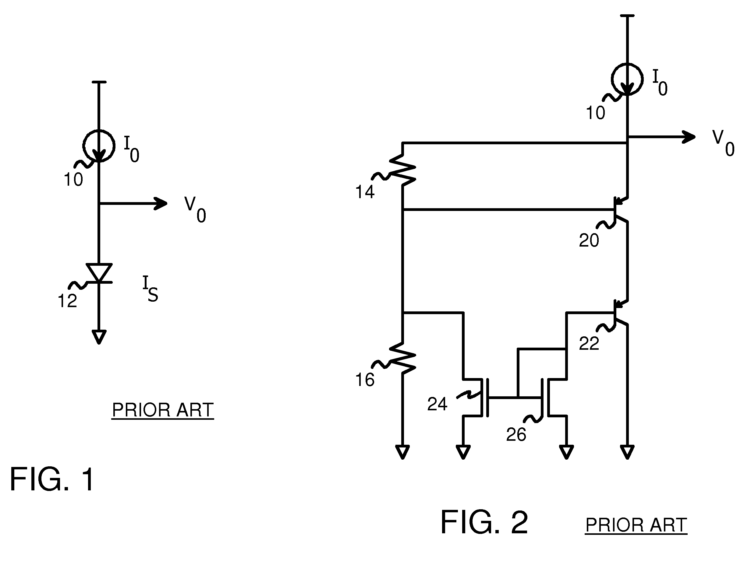
A drawback of the simple circuit in FIG. 1 is that a constant current source 10 is needed.
Linearity of the output voltage with temperature can be degraded due to non-ideal characteristics of real current sources.
Also, the amount of temperature sensitivity is relatively small.
Unfortunately, an ideal current source 10 is still needed, and a BiCMOS process is used.
This reduced headroom can be a problem for reduced power-supply voltages.
A temperature sensor that scales temperature sensitivity using a resistor ratio, a current-minor ration, or other methods, but does not have a reduced voltage headroom is desirable.

Method used


Image

  • CMOS Temperature Sensor with Sensitivity Set by Current-Mirror and Resistor Ratios without Limiting DC Bias
  • CMOS Temperature Sensor with Sensitivity Set by Current-Mirror and Resistor Ratios without Limiting DC Bias
  • CMOS Temperature Sensor with Sensitivity Set by Current-Mirror and Resistor Ratios without Limiting DC Bias

Examples


Embodiment Construction

[0020]The present invention relates to an improvement in temperature sensing circuits. The following description is presented to enable one of ordinary skill in the art to make and use the invention as provided in the context of a particular application and its requirements. Various modifications to the preferred embodiment will be apparent to those with skill in the art, and the general principles defined herein may be applied to other embodiments. Therefore, the present invention is not intended to be limited to the particular embodiments shown and described, but is to be accorded the widest scope consistent with the principles and novel features herein disclosed.

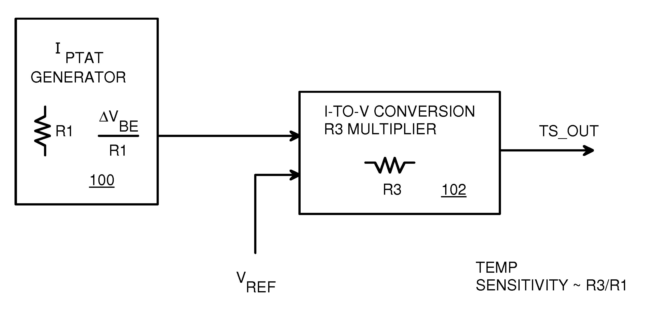
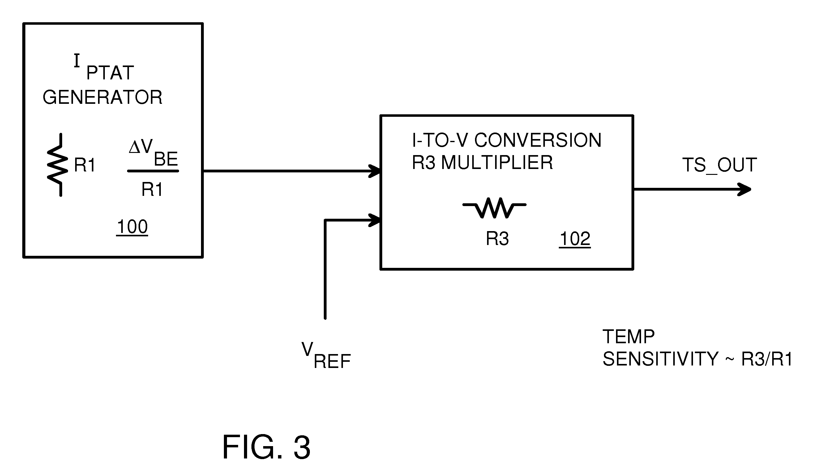
[0021]FIG. 3 is a block diagram of a temperature sensing circuit. IPTAT generator 100 is a circuit that generates a current that is Proportional To Absolute Temperature (PTAT). However, rather than use a single diode, or a single base-emitter junction in a transistor, two transistors are used, and the resulting voltages s...


PUM


Abstract

An on-chip temperature sensor circuit can be implemented in a standard complementary metal-oxide-semiconductor (CMOS) process using PNP transistors. A pair of transistors have collector currents that are sensitive to voltage, both directly and due to saturation currents. A scaling resistor connects to the emitter of one transistor and its voltage compared to the other transistor's emitter voltage by an error amplifier that generates a bias voltage to current sources that are proportional to absolute temperature since the saturation current sensitivity is subtracted out. The current is mirrored to sink current through a multiplier resistor from an output. An amplifier connected across the multiplier resistor compares a reference voltage to set the DC bias independent of temperature sensitivity. The temperature sensitivity is proportional to the ratio of the multiplier resistor and the scaling resistor, and is multiplied by a mirroring factor. A differential output may also be provided.

Description

FIELD OF THE INVENTION[0001]This invention relates to temperature sensors, and more particularly to on-chip CMOS temperature sensor circuits.BACKGROUND OF THE INVENTION[0002]High levels of integration of circuits has produced large chips that can perform many tasks. However, the tightly packed transistors generate heat, especially at higher operating frequencies. Hotspots on the chip can cause erratic circuit function or even permanent damage.[0003]Temperature-monitoring circuits can be added to the integrated circuit (IC) chip. Such on-chip temperature monitor circuits may detect high temperatures and activate a power controller to power down some or all of the chip's circuits, or perhaps reduce the operating frequency. Once the temperature falls sufficiently, the circuits may be powered back up or resume operation.[0004]Ideally such temperature monitoring circuits use the same process technology as the other circuits on the chip. However, some temperature monitoring circuits requi...

Claims


Application Information

Patent Timeline
IPC IPC(8): G01K7/01
CPCH01L35/32G01K7/01H10N10/17
Inventor WONG, CHUN FAICHAN, KAM HUNG
Owner HONG KONG APPLIED SCI & TECH RES INST
Learn More