Magnetic Pulse Formed Vehicle Driveshaft and Method of Making Same

a technology of magnetic pulse and drive shaft, which is applied in the direction of manufacturing tools, mechanical equipment, couplings, etc., can solve the problems of difficult deep elongation, difficult to form parts, and practically impossible to form most types of steel without a driver, so as to simplify the sliding spline-type slip joint of the driveshaft and eliminate the effect of electric erosion of the working mandrel surfa

Inactive Publication Date: 2013-09-12
DANA AUTOMOTIVE SYST GRP LLC
View PDF7 Cites 9 Cited by
  • Summary
  • Abstract
  • Description
  • Claims
  • Application Information

AI Technical Summary

Benefits of technology

[0011]In accordance with the present invention, it is highly desirable to develop a driveshaft design and manufacturing process capable of utilizing the advan...

Problems solved by technology

The basic disadvantages of magnetic pulse forming are: it is hard to perform deep elongation; it is practically impossible to form most types of steel without a driver and impossible to form parts when the free passage of electric current is restricted.
However, it is hard to realize the described technique in practice, especially under the high volume production conditions typical for manufacturing driveshafts.
As a result, very high opposing currents will be induced along...

Method used


Image

  • Magnetic Pulse Formed Vehicle Driveshaft and Method of Making Same
  • Magnetic Pulse Formed Vehicle Driveshaft and Method of Making Same
  • Magnetic Pulse Formed Vehicle Driveshaft and Method of Making Same

Examples


example

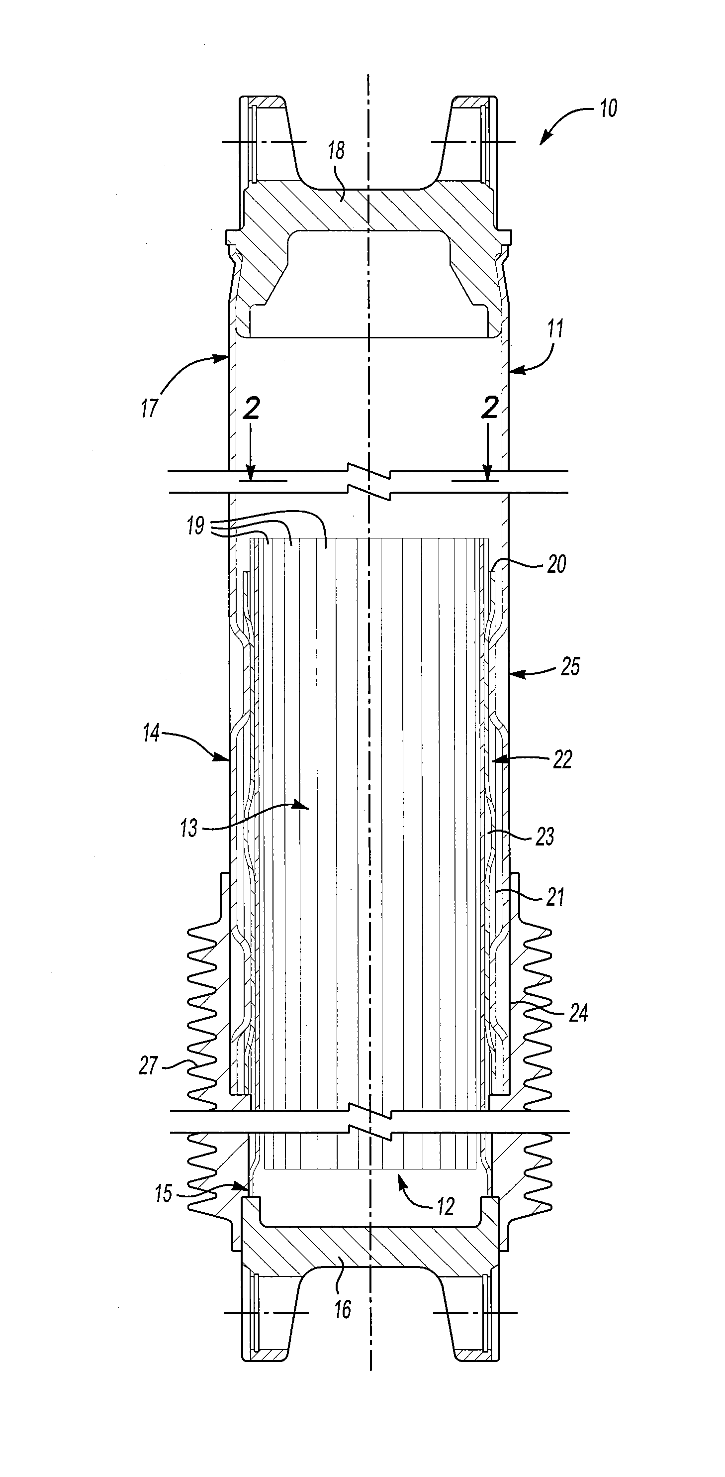
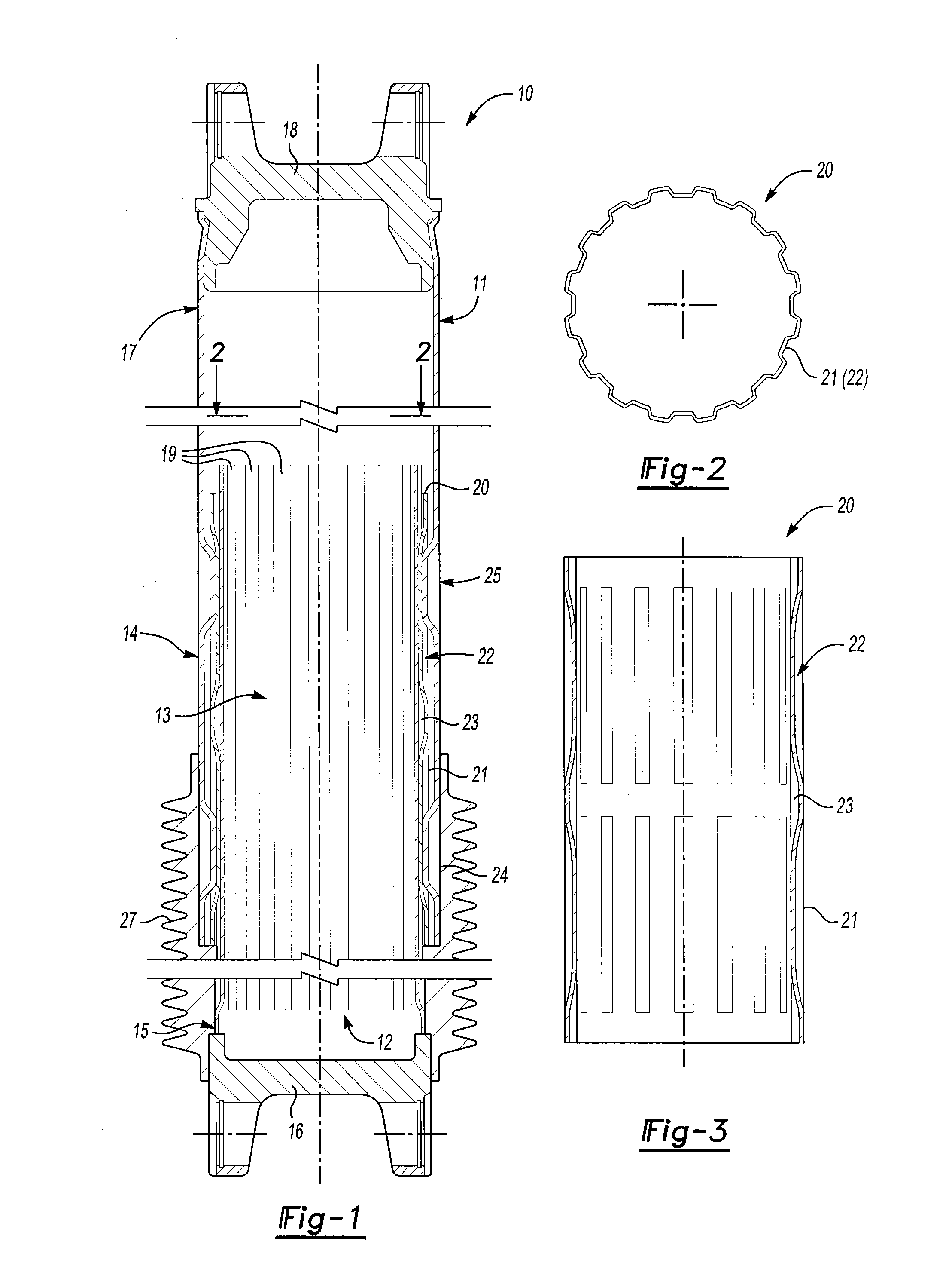
[0053]The second end portion 17 of the female driveshaft tube 11 with an outer diameter 114 mm, a wall thickness 2.5 mm and made from aluminum 6061T6 alloy was welded according with the present invention to the second yoke 18 made from aluminum 6061T6 alloy. The first end portion 14 of the female driveshaft tube 11 was connected with the Grob processed insert 20b (see FIG. 8) by means of two rows of magnetic pulse formed crimps 24, 25 axially spaced at 90 mm from each other. Both, the welding and crimping operations were performed in three stages exactly as described above and shown in FIG. 9 with the help of semiautomatic pneumatically actuated tooling and proper pulse power and induction heating equipment.

[0054]The one-turn pulse inductor coil 41 and the control circuit 40 (see FIG. 9) were made in accordance with U.S. Pat. No. 4,129,846. The capacitor 45 had a capacitance of 8.4 mF, maximal voltage U=5 kV and maximal energy of charging 105 kJ. The discharge circuit had a frequenc...


PUM

PropertyMeasurementUnit
Plasticityaaaaaaaaaa

Abstract

A method of forming a sliding spline-type joint using magnetic pulse forming technology includes providing a female driveshaft member and a splined insert having inwardly formed splines. A male driveshaft member is provided having outwardly formed splines engageable with the insert. A mandrel is provided having outer ribs similar to the outer spline profile of the male driveshaft member. An inductor is provided which is energized to create a pulse magnetic field. The insert is placed over the mandrel. The female driveshaft member is disposed over the insert, and both are placed inside the inductor. The inductor is energized to deform a portion of the female driveshaft member over the insert to form an array of crimps for permanently connecting the female driveshaft member with the insert. The male driveshaft member is engaged into the insert to provide a sliding spline-type of slip joint.

Description

RELATED APPLICATIONS[0001]Not ApplicableFIELD OF THE INVENTION[0002]This invention relates to vehicular driveshaft assemblies and in particular to a method of forming a sliding spline-type joint using magnetic pulse forming technology.BACKGROUND OF THE INVENTION[0003]The present invention relates to a driveshaft design and method of making same, capable of utilizing the advantages of magnetic pulse forming technology to simplify a driveshaft sliding spline-type joint and to eliminate electric erosion of the active working mandrel surface.[0004]Torque transmitting shafts (driveshafts) are widely used for transferring rotational power from a source of rotational power to a rotatably driven mechanism. For example, in most land vehicles in use today, a drive train system is provided for transmitting rotational power from an output shaft of an engine / transmission assembly to an output shaft of an axle assembly so as to rotatably drive the wheels of the vehicle. To accomplish this, a typi...

Claims


Application Information

Patent Timeline
IPC IPC(8): F16D1/02B23P17/04
CPCF16D1/068F16D1/0858F16D2250/0061F16D2250/0076Y10T29/49803F16D3/06F16D2300/12Y10T403/7026B23K20/06F16C3/03
Inventor YABLOCHNIKOV, BORIS A.SMITH, JOHNNY N.
Owner DANA AUTOMOTIVE SYST GRP LLC
Why Eureka
Try Eureka