Low Pressure Compressor Variable Vane Control for Two-Spool Turbofan or Turboprop Engine

a variable vane control and compressor technology, applied in the direction of machines/engines, reaction engines, liquid fuel engines, etc., can solve the problems of detracting from the performance and efficiency of the engine, lacking control schemes for variable stator vanes, etc., and achieve the effect of higher performan

Active Publication Date: 2013-09-12
RAYTHEON TECH CORP +1
View PDF4 Cites 21 Cited by
  • Summary
  • Abstract
  • Description
  • Claims
  • Application Information

AI Technical Summary

Benefits of technology

[0009]In an aspect, the system for adjusting an angle of at least one stator vane of a low pressure compressor (LPC) of a two spool gas turbine engine is disclosed. The system includes at least one stator vane rotatably coupled to a stationary case and directed inwardly along a radius of the case. The system also includes an actuator coupled to at least one stator vane for imparting rotation to the stator vane about said radius. The actuator is linked to a controller. The controller includes a memory stored with constraints defined by corresponding LPC compressor pressure ratios and LPC compressor corrected air flows. The controller sends a signal to rotate at least one stator vane to alter at least one of the compressor pressure ratio or compressor corrected air flow values to change the current operating condition of the LPC to a target operating condition such that the engine remains within its stability constraint.
[0010]In another aspect, a system is disclosed for adjusting an angle of least one stator vane of a low pressure compressor of a two spool gas turbine engine. The disclosed system includes at least one stator vane being rotatably coupled to a circular stationary case and directed inwardly along a radius of the case. The system also includes an actuator coupled to at least one stator vane for imparting rotation to the stator van...

Problems solved by technology

However, schemes for controlling variable stator vanes are generally lacking.
Engines without LPC variable stator ...

Method used


Image

  • Low Pressure Compressor Variable Vane Control for Two-Spool Turbofan or Turboprop Engine
  • Low Pressure Compressor Variable Vane Control for Two-Spool Turbofan or Turboprop Engine
  • Low Pressure Compressor Variable Vane Control for Two-Spool Turbofan or Turboprop Engine

Examples


Embodiment Construction

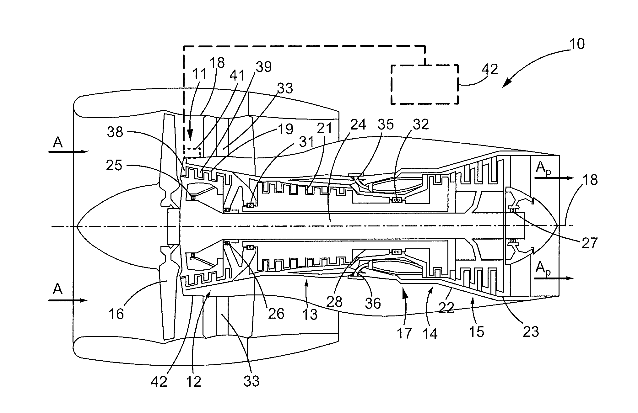
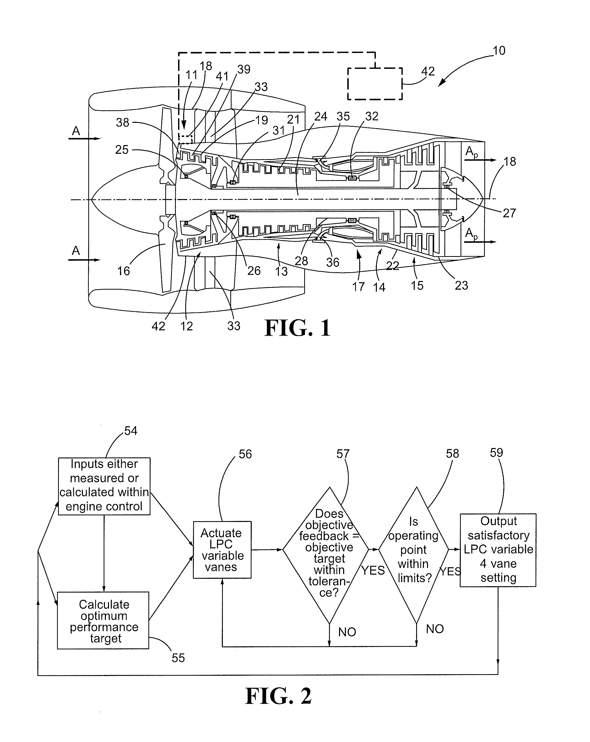
[0015]FIG. 1 shows a schematic cross section of a gas turbine engine 10 which includes a variable vane actuation mechanism 11. In the embodiment shown, the gas turbine engine 10 includes a dual-spool high bypass ratio turbofan engine having a variable vane turbine section that incorporates the actuation mechanism 11. In other embodiments, the gas turbine engine 10 may be another type of gas turbine engine used for aircraft propulsion or power generation, or other systems incorporating variable stator vanes. Although the actuation mechanism 11 is well suited for the low pressure compressor (LPC) 12, the disclosed system is readily applicable to the high pressure compressor (HPC) 13, the high pressure turbine (HPT) 14 as well as the low pressure turbine (LPT) 15.

[0016]The operating principals of the gas turbine engine 10 are well known in the art. Briefly, the gas turbine engine 10 includes a fan 16, followed by the LPC 12, HPC 13, combustor section 17, HPT 14, and LPT 15, all of whic...


PUM

PropertyMeasurementUnit
Temperatureaaaaaaaaaa
Ratioaaaaaaaaaa

Abstract

A system and a method for adjusting an angle of at least one stator vane of a low pressure compressor (LPC) of a two spool gas turbine engine is disclosed. Variable stator vanes are rotatably coupled to a stationary case in one of the stages of the LPC. An actuator is coupled to at least one of the variable stator vanes for imparting rotation of the stator vane about a radius of the case. Various coupling or linkage arrangements may be made so that rotation of one vane results in rotation of the other vanes disposed along the case. The controller includes the stored constraints, the ability to estimate operating condition, and the ability to estimate optimum targets.

Description

TECHNICAL FIELD[0001]This disclosure relates to gas turbine engines, and more particularly to dual-spool turbofan or turboprop engines. Still more specifically, this disclosure relates to variable stator vanes of the low pressure compressor (LPC) of such engines and control schemes for such variable stator vanes.BACKGROUND[0002]Two spool turbofan and turboprop jet engines typically include three sections in the core. The first section is the compressor section, which includes a low pressure compressor (LPC) followed by a high pressure compressor (HPC). A combustor section is disposed between the compressor section and a turbine section, which includes a high pressure turbine (HPT) followed by a low pressure turbine (LPT). The LPT is connected to and drives the LPC via one shaft and the HPT is connected to the HPC via a second shaft.[0003]Turbofan and turboprop engines operate by combusting fuel in air that has been compressed by the LPC and HPC of the compressor section. The combust...

Claims


Application Information

Patent Timeline
IPC IPC(8): F01D17/00B23P17/00
CPCY10T29/49229F02C9/20
Inventor COLLOPY, GARYFEULNER, MATTHEW R.
Owner RAYTHEON TECH CORP
Why Eureka
Try Eureka