System and Method for Cache Organization in Row-Based Memories

a cache and row-based memory technology, applied in the field of cache organization, can solve the problems of increasing observed memory access latencies, reducing memory bank availability, and consuming energy in the bit cell array, so as to reduce the number of activations, improve cache performance, and reduce power consumption

Active Publication Date: 2013-09-12
ADVANCED MICRO DEVICES INC
View PDF16 Cites 27 Cited by
  • Summary
  • Abstract
  • Description
  • Claims
  • Application Information

AI Technical Summary

Benefits of technology

[0024]Among other advantages, some embodiments of the method and system of the present disclosure provide a cache organization strategy that reduces the power consumption and improves performance of the cache by reducing the number of activations and precharges required to access the data stored in the cache. By organizing data in the cache such that a

Problems solved by technology

In some row-based memories, such as DRAM, for example, the data in the row buffer is written back to the bit cell array after the read/write operation or access is complete because the original activation operation often destroys the charges (i.e., data) stored in the activated row.
Each activation and precharge of the bit cell array consumes energy, increases observed memory access latencies, and reduces memory bank availability.
With the cache line organization of FIG. 2, long sequences of sequential cache line accesses cause repeated activations and precharges, thereby increasing the total access latencies.
Further, larger cache line sizes may lead to an increase in false sharing for cache coherent systems.
If core Y is only accessing data at A1 rather than at A0, then invalidation of the entire cache line wastes power and increases latency because core Y only needed to invalidate the data block at address A0, i.e., because the data at A1 was still up-to-date.
Further, memory bandwidth consumption is increased, as the data at both A0 and A1 is transferred even if only one of A0 and A1 is used.
Further still, some portions of the cache line in the accessed row may not be needed but still take up memory space, leading to fragmentation in which unused data blocks occupy cache memory.
In particular, memory bandwidth may be wasted when, for example,

Method used


Image

  • System and Method for Cache Organization in Row-Based Memories
  • System and Method for Cache Organization in Row-Based Memories
  • System and Method for Cache Organization in Row-Based Memories

Examples


Embodiment Construction

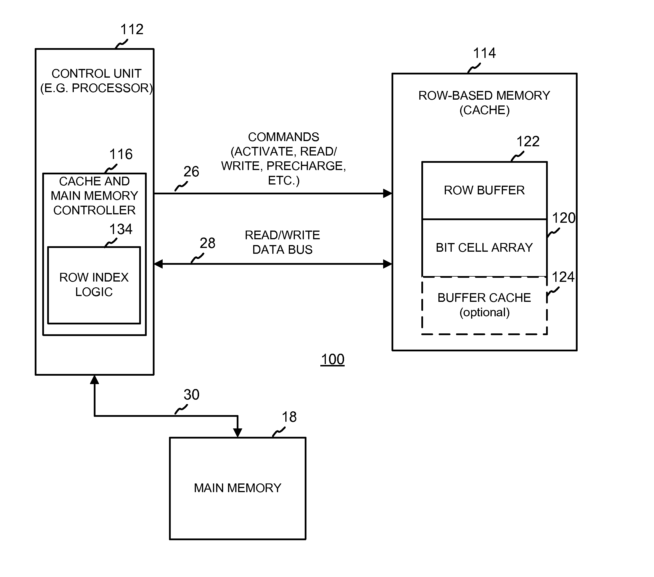
[0023]In an exemplary embodiment of the present disclosure, a method for mapping cache lines to a row based cache is provided. The method includes, in response to a plurality of memory access requests each including an address associated with a cache line of a main memory, mapping a plurality of sequentially addressed cache lines of the main memory to a row of the row-based cache.

[0024]Among other advantages, some embodiments of the method and system of the present disclosure provide a cache organization strategy that reduces the power consumption and improves performance of the cache by reducing the number of activations and precharges required to access the data stored in the cache. By organizing data in the cache such that a number of sequentially addressed cache lines are stored in the same cache row, data from spatially local cache lines is retrieved from the cache more efficiently, for example. Another exemplary advantage is that set associativity is improved while avoiding fr...


PUM


Abstract

The present disclosure relates to a method and system for mapping cache lines to a row-based cache. In particular, a method includes, in response to a plurality of memory access requests each including an address associated with a cache line of a main memory, mapping sequentially addressed cache lines of the main memory to a row of the row-based cache. A disclosed system includes row index computation logic operative to map sequentially addressed cache lines of a main memory to a row of a row-based cache in response to a plurality of memory access requests each including an address associated with a cache line of the main memory.

Description

FIELD OF THE DISCLOSURE[0001]The present disclosure is generally related to the field of cache organization, and more particularly to methods and systems for mapping cache lines to a row-based cache.BACKGROUND[0002]Computing systems include one or more memories for storing data and other information in the form of bits. Many computing systems include both a main or primary memory and a cache memory. The main memory, which may include one or more memory structures or storage mediums, stores data and instructions that are executed by a processor (e.g., CPU) or other control unit of the computing system. Some main memories include volatile random access memories (RAM), although other suitable memory types may be provided. The cache memory, which also may include one or more memory structures or storage mediums, is often used by a processor of the computing system to temporarily store copies of data from the main memory to reduce the time or latency required for the processor to access ...

Claims


Application Information

Patent Timeline
IPC IPC(8): G06F12/08
CPCG06F12/0882G06F12/0864
Inventor LOH, GABRIEL H.HILL, MARK D.
Owner ADVANCED MICRO DEVICES INC
Why Eureka
Try Eureka