Work vehicle with engine mounted rearwardly

Active Publication Date: 2013-09-19
KUBOTA LTD
View PDF2 Cites 3 Cited by
  • Summary
  • Abstract
  • Description
  • Claims
  • Application Information

AI Technical Summary

Benefits of technology

[0006]With the above-noted arrangement, the fuel tank is divided into the main tank body and the auxiliary tank body that are provided spacious areas, respectively, such as under the driver's seat and the side of the engine, as a result of which good efficiency of spatial use can be achieved. Further, the fuel tank, vertical engine and canister are adjacently provided so that they do not substantially overlap each other as viewed from the top. Since the particularly heavy engine is provided vertically in the central portion in the transverse direction of the vehicle, the stability of the work vehicle is secured. Further, the engine, fuel tank and canister are adjacently disposed, which can diminish a piping layout extending between those devices. In addition, the fuel tank is divided into the main tank body mounted under the driver's seat and the a

Problems solved by technology

In such a conventional fuel system, it is required to provide long hoses for connecting between the fuel tanks, canisters and engine, which results in a complicated hose arrangement.
In this arrangement, the cani

Method used


Image

  • Work vehicle with engine mounted rearwardly
  • Work vehicle with engine mounted rearwardly
  • Work vehicle with engine mounted rearwardly

Examples


Embodiment Construction

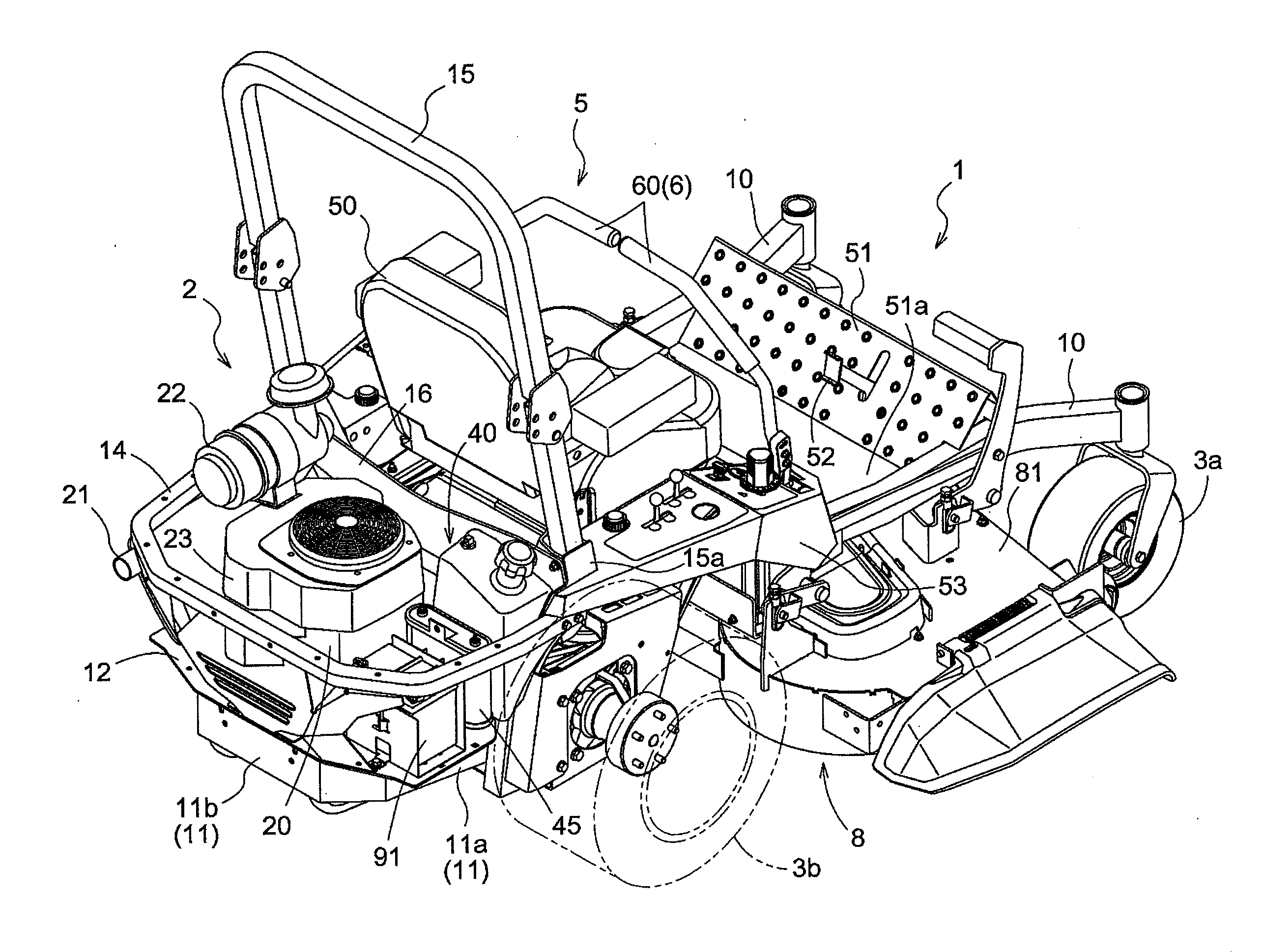
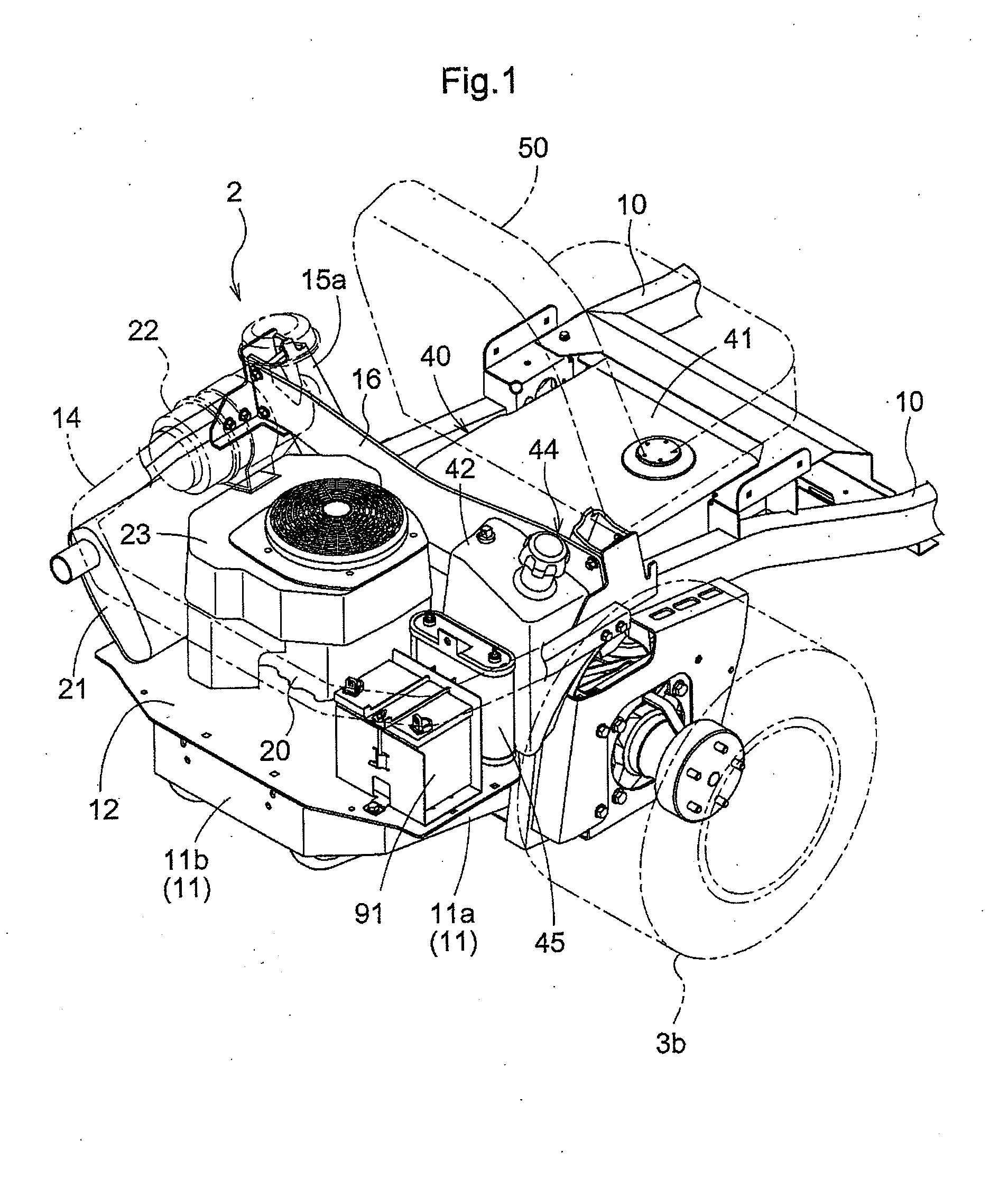
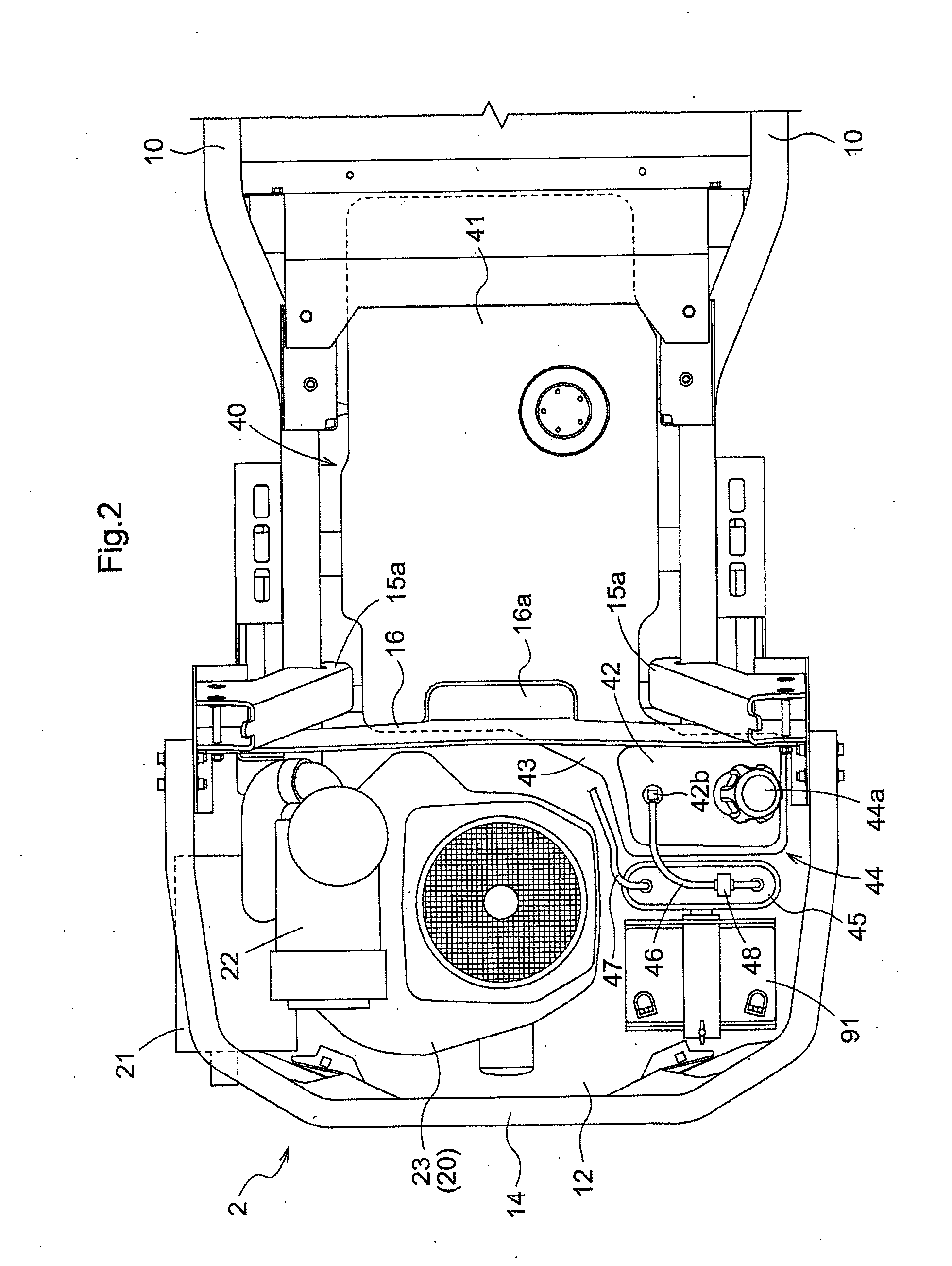
[0023]Prior to describing specific embodiments of a work vehicle according to the present invention, a basic arrangement of an engine and a fuel system mounted in a rear area of the vehicle will be described first in reference to schematic views shown in FIGS. 1 and 2.

[0024]In the rear area of the vehicle are included a right and left pair of rear wheels 3b and a rear frame 11 acting as a vehicle frame extending between the rear wheels 3b. A driver's seat 50 is arranged slightly forwardly of a center of an axle of the rear wheels, which is only partially depicted in two-dot chain line to provide good visibility for other devices.

[0025]A substantially horizontal mounting surface 12 is defined in the rear frame 11 in a peripheral area of the rear wheels 3b, which is formed of a floor material mounted on the rear frame 11 in this example. The engine 20 is mounted in a vertical position, with an output shaft thereof being directed downward, on the mounting surface 12 in a central portio...


PUM


Abstract

A work vehicle includes a vehicle frame extending between a right and left pair of rear wheels. An engine is mounted in a vertical position on a horizontal mounting surface defined in the vehicle frame in a peripheral area of the rear wheels in a central portion of a transverse direction of the vehicle. A fuel tank includes a main tank body mounted under a driver's seat and an auxiliary tank body mounted on the mounting surface on one lateral side of the engine in the transverse direction of the vehicle. A canister is mounted adjacent to the engine on one lateral side of the engine and rearwardly of and adjacent to the auxiliary fuel tank.

Description

TECHNICAL FIELD[0001]The present invention relates to a work vehicle including an engine and a fuel system mounted in a rear area of a vehicle frame extending between a right and left rear wheels rearwardly of a driver's seat.BACKGROUND ART[0002]U.S. Patent Application Publication No. US 2010 / 0242924 discloses a lawn mower including a rear frame formed of a right and left pair of side members made of sheet metal and a mounting surface supported rearwardly of the right and left side members, for example. An air-cooled engine is mounted on the mounting surface with an output shaft thereof projecting forward of a vehicle body. A muffler is disposed in a transverse position rearwardly of the engine. Fuel tanks are provided above the right and left rear wheels, respectively, to act as a fuel system. Evaporated gas separator tanks and canisters are disposed between the fuel tanks and the engine to allow fuel gas evaporated within the fuel tanks to combust in the engine. Each of the evapor...

Claims


Application Information

Patent Timeline
IPC IPC(8): B60K8/00B60K15/03B60K13/04
CPCB60K15/06B60K15/063B60K2015/03118B60K2015/03151B60Y2200/223B60K2015/03514B60K2015/0632B60K2015/0638B60K15/03177
Inventor SPITZ, DAVIDYAMADA, MASAHIROKOMORIDA, TAKESHISHIBATA, TAKASHI
Owner KUBOTA LTD
Why Eureka
Try Eureka