Driving device, light-emitting device and projector

Active Publication Date: 2013-09-19
CASIO COMPUTER CO LTD
View PDF3 Cites 6 Cited by
  • Summary
  • Abstract
  • Description
  • Claims
  • Application Information

AI Technical Summary

Benefits of technology

The technical effect of this patent text is to prevent a delay in the response of an output current and / or voltage from a power source in a load-selected period after a light-out period.

Problems solved by technology

Such a phenomenon results in a delay in the response of the output voltage and / or the output current from the switching regulator in the subsequent load-selected period.

Method used


Image

  • Driving device, light-emitting device and projector
  • Driving device, light-emitting device and projector
  • Driving device, light-emitting device and projector

Examples


first embodiment

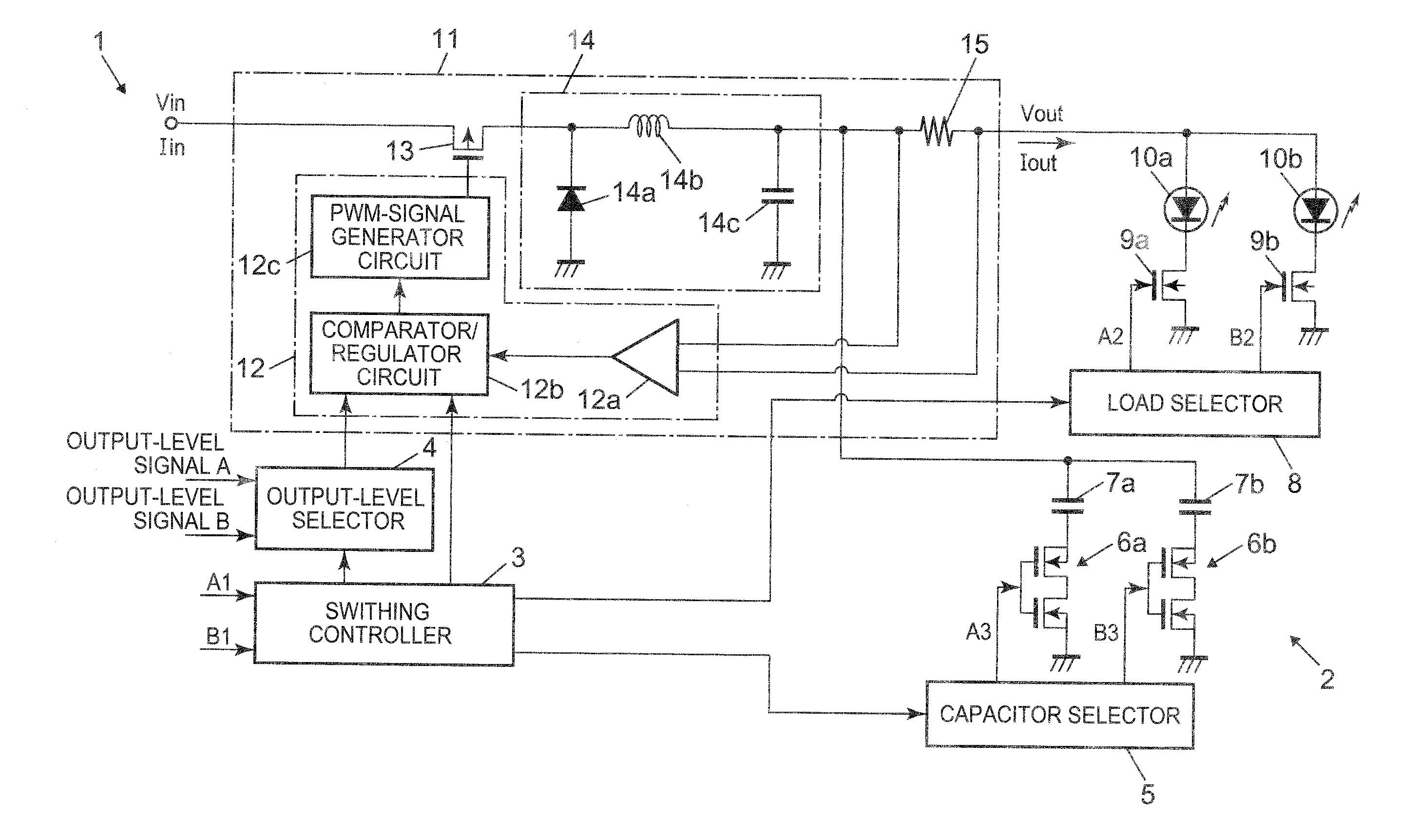
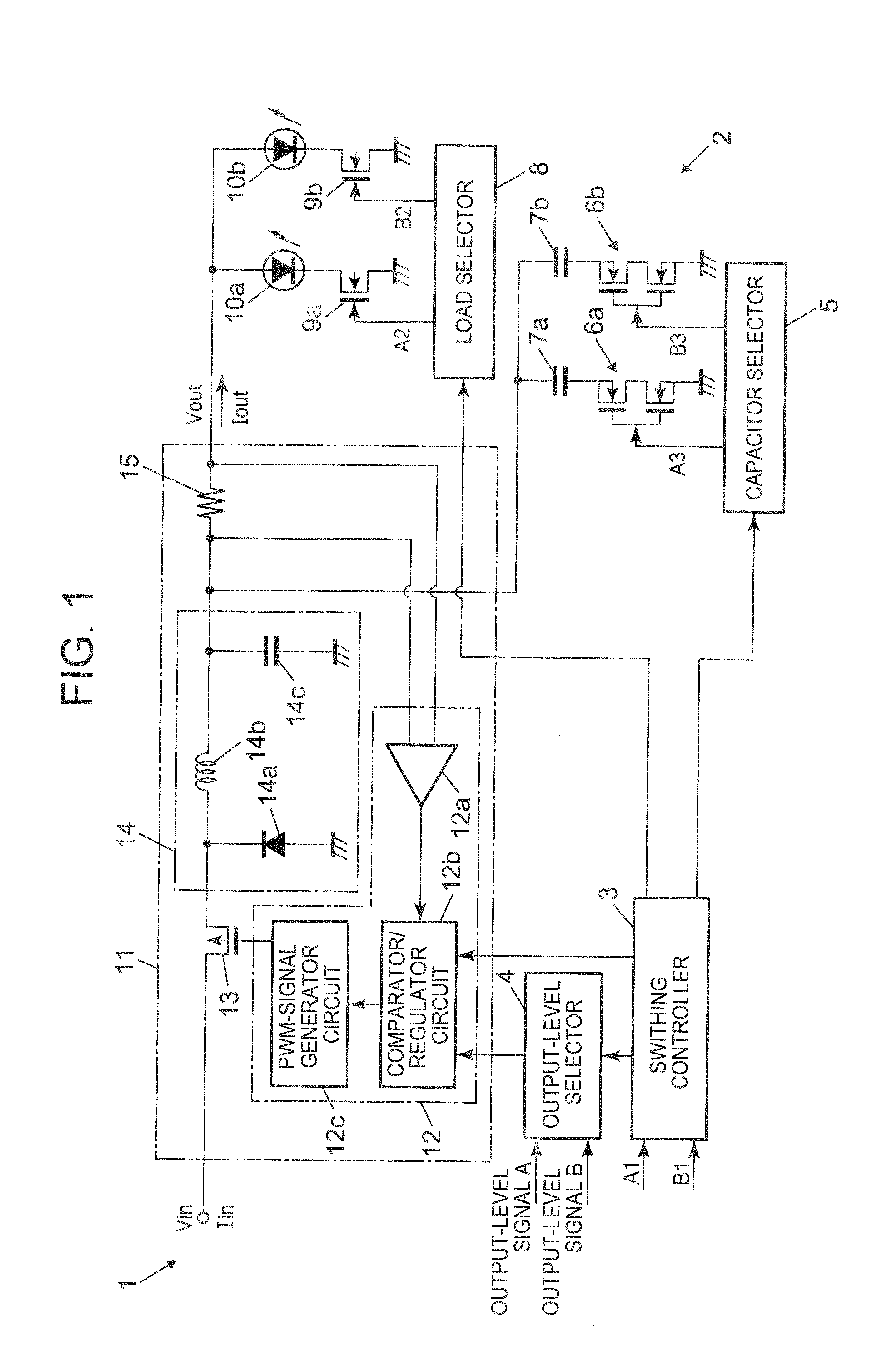
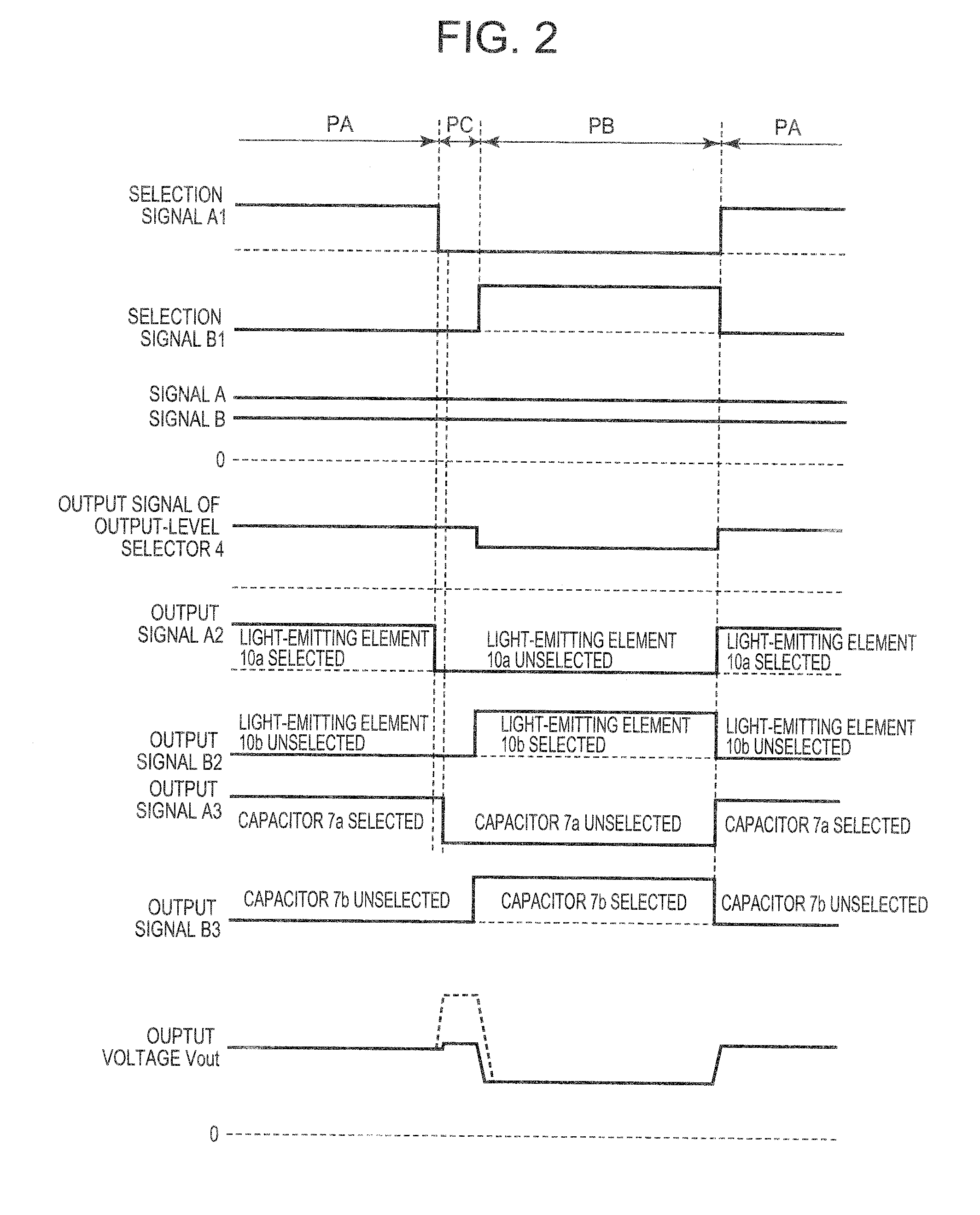
[0020]FIG. 1 is a circuit diagram of a sequential color light-emitting device 1. FIG. 2 is a timing chart illustrating the signal waveforms of the individual components included in the sequential color light-emitting device 1.

[0021]The sequential color light-emitting device 1 includes light-emitting elements 10a and 10b, a switching controller 3, an output-level selector 4, a capacitor selector 5, switches 6a and 6b, capacitors 7a and 7b, a load selector (light-emitting-element selector) 8, semiconductor switching elements 9a and 9b, and a switching regulator 11 serving as a power source (power circuit or power converter).

[0022]A driving device 2 is a circuit including the switching controller 3, the output-level selector 4, the capacitor selector 5, the switches 6a and 6b, the capacitors 7a and 7b, the load selector 8, the semiconductor switching elements 9a and 9b, and the switching regulator (DC-DC converter) 11. The driving device 2 is applied to the sequential color light-emitt...

first modification

[First Modification]

[0073]In the embodiment described above, the switching regulator 11 is of a buck type. Alternatively, the switching regulator 11 may be of a boost type or a buck-boost type. In other words, the circuitry of the switching element 13 and smoothing circuit 14 may be modified to a boost or buck-boost type.

second modification

[Second Modification]

[0074]In the embodiment described above, the switching regulator 11 is of a non-isolated type. Alternatively, the switching regulator 11 may be of an isolated type.


PUM


Abstract

A driving device includes a power source that converts input power to output power, first and second capacitors connected to an output of the power source, a load selector, and a capacitor selector. The load selector opens / closes circuits of first and second loads connected to the output of the power source to alternately close these circuits such that the second-load circuit is closed after the opening of the first-load circuit. The capacitor selector opens / closes circuits of the first and second capacitors to alternately close these circuits such that the first-capacitor circuit is closed in synchronization with the closing of the first-load circuit, and such that the second-capacitor circuit is closed in synchronization with the closing of the second-load circuit. The capacitor selector opens the first-capacitor circuit after the opening of the first-load circuit.

Description

BACKGROUND OF THE INVENTION[0001]1. Field of the Invention[0002]The present invention relates to a driving device, a light-emitting device and a projector.[0003]2. Description of Related Art[0004]For example, a switching regulator (switching power source or DC-DC converter), serving as a power source, is a circuit that converts a DC input voltage to a DC output voltage through a turning on / off operation of a switching element and is used as a power source or driver having various loads. The output current or voltage from the switching regulator is controlled by a feedback control system so as to be maintained at a constant target value.[0005]Electric power can be supplied in sequence from a single switching regulator to a plurality of loads through sequential selection of the loads with a selector installed at the output of the switching regulator (for example, refer to FIG. 25 in Japanese Patent Application Laid-Open No. 2004-311635).[0006]If different currents are supplied to indi...

Claims


Application Information

Patent Timeline
IPC IPC(8): H02J1/00H05B37/02H05B44/00
CPCH02J1/00H05B33/0815H05B33/0803H05B37/02H05B47/10H05B45/345H05B45/3725H05B45/36H05B45/38H05B45/325H05B45/392
Inventor SUZUKI, HIDEO
Owner CASIO COMPUTER CO LTD
Why Eureka
Try Eureka