
Covalently dimerized bivalent binding agents

a bivalent, binding agent technology, applied in the field of binding agents, can solve the problems of reducing the potency of the trap, fibrotic disorders, severe disease pathologies,

Inactive Publication Date: 2013-09-26
NAT RES COUNCIL OF CANADA
View PDF1 Cites 9 Cited by
  • Summary
  • Abstract
  • Description
  • Claims
  • Application Information

AI Technical Summary

Benefits of technology

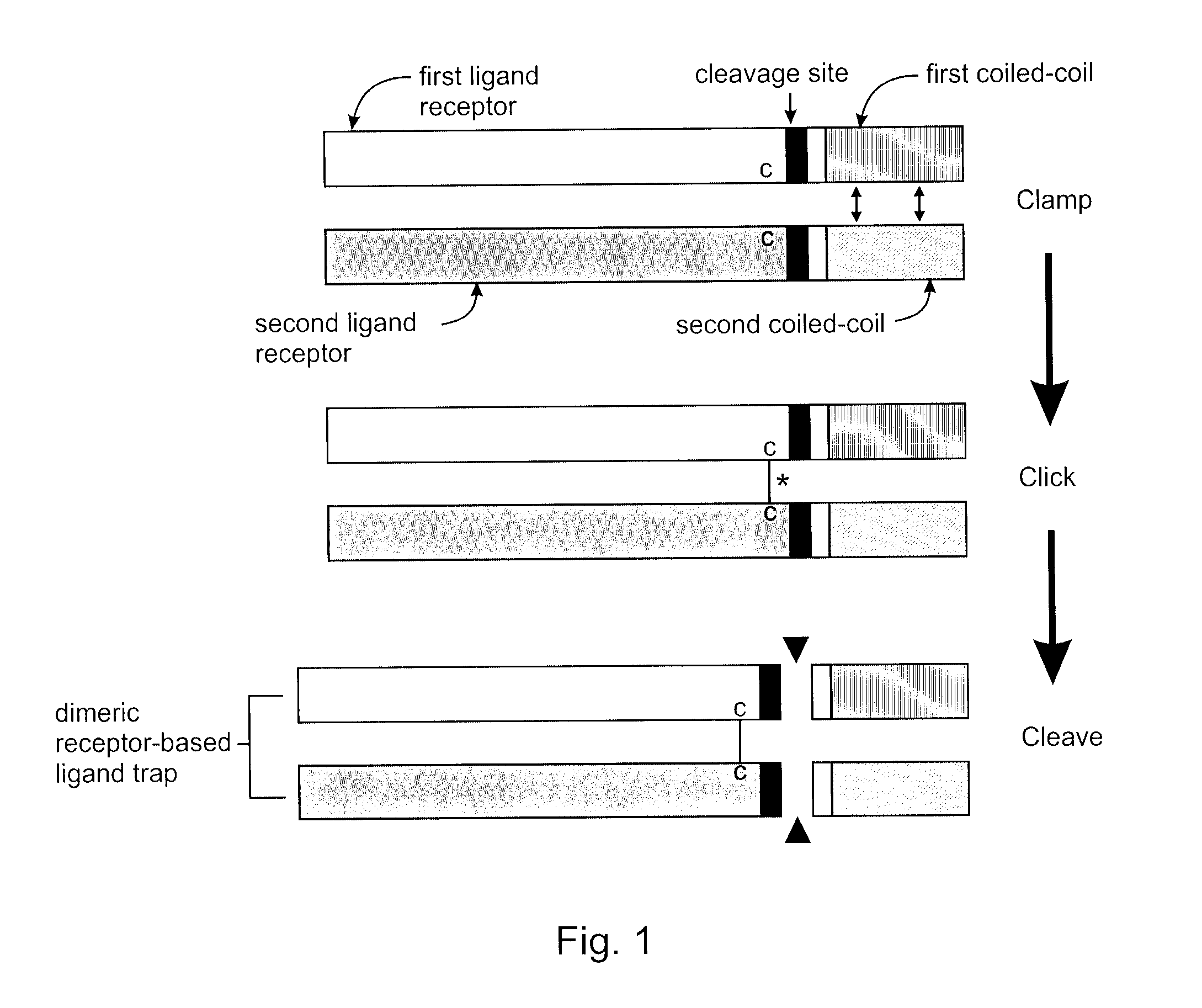
The present invention provides a method for producing a covalently dimerized bivalent binding agent and a covalently dimerized receptor-based ligand trap that can be used to treat disease states. The method involves fusing a first coiled-coil with a first binding domain and a first cysteine residue, and a second coiled-coil with a second binding domain and a second cysteine residue. The two fusion proteins are then mixed and cleaved at the cleavage sites to produce the covalently dimerized bivalent binding agent or receptor-based ligand trap with a disulphide bond between the two cysteine residues. The technical effect of this invention is the production of a more stable and effective binding agent that can be used to treat disease states.

Problems solved by technology

Nevertheless, deregulated TGF-β activity results in severe disease pathologies.
In other cases, TGF-β overexpression leads to fibrotic disorders due to abnormal extracellular matrix accumulation.
Nevertheless, two drawbacks of the coiled-coil system are 1) the non-covalent nature of coil dimerization may lead to separation of the receptor chains in the blood of the injected host, hence reducing trap potency and 2) the artificial coils may be immunogenic.

Method used


Image

  • Covalently dimerized bivalent binding agents
  • Covalently dimerized bivalent binding agents
  • Covalently dimerized bivalent binding agents

Examples


example 1

Homodimeric TGF-β RII-Coil Trap Dimers

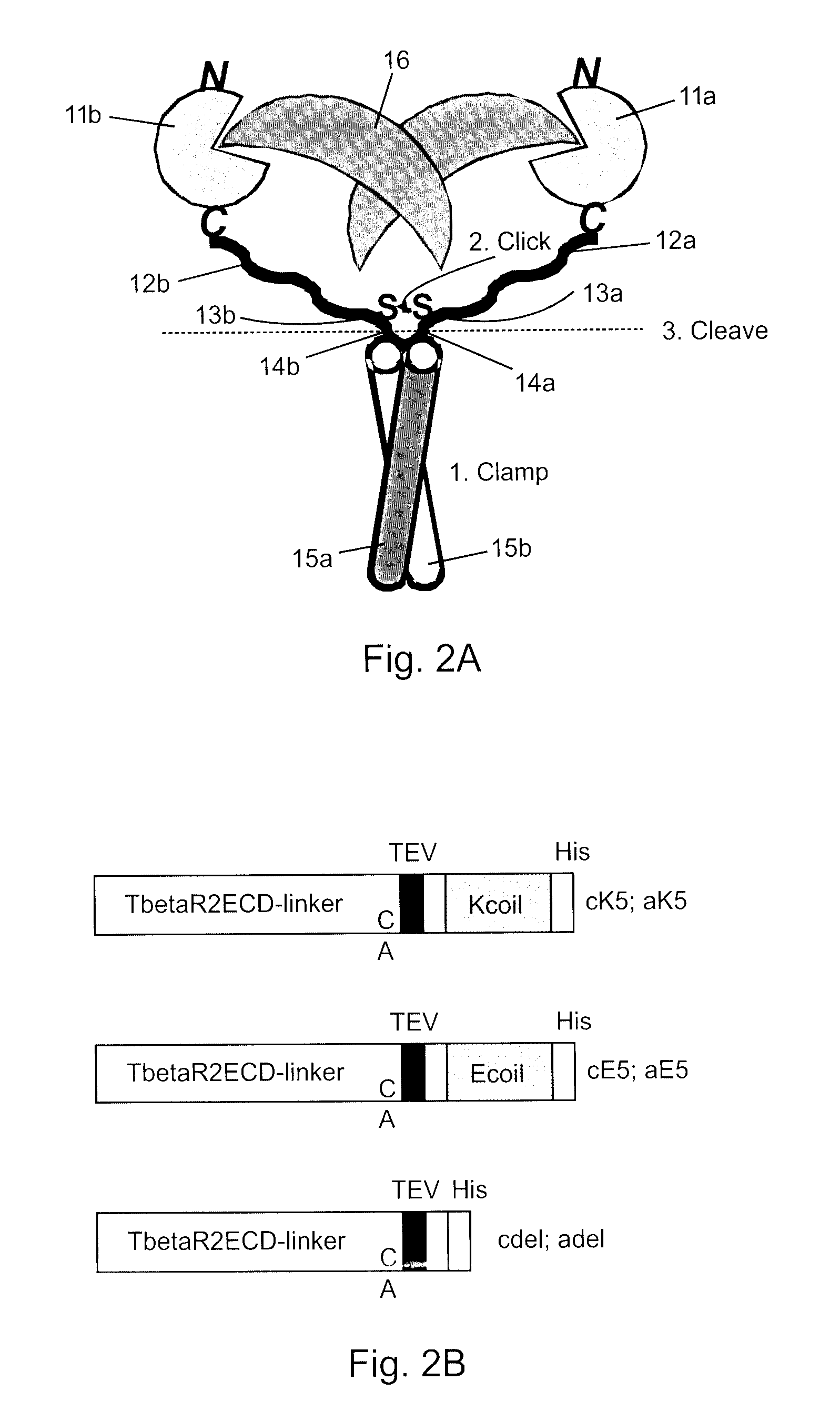
[0056]With reference to FIG. 2A and FIG. 2B, in this example fusion peptides are constructed as described above comprising TGF-β RII ectodomains (TβR2ECD) 11a,b with N-terminal signal sequences, short first linker sequences 12a,b, cysteine residues 13a,b, short second linker sequences (not labeled), TEV cleavage sites 14a,b, short third linker sequences (not labeled), either E5 coil sequence 15a or K5 coil sequence 15b, short fourth linker sequences (not labeled), and 6×His tags at the C-terminal ends. When these peptides are mixed together the E and K coils promote non-covalent dimerization (step 1, clamp) and the formation of an interchain disulfide bond (step 2, click) to form a trap dimer of the present invention. The coils are subsequently excised by TEV protease cleavage (step 3), producing a covalently linked, homobivalent TGF-β trap of the present invention that is free of the artificial coils. Using this method the TGF-β RII receptors a...

example 2

TGF-β RI-Coil and TGF-β RII-Coil Fusion Constructs with Cysteine on the C-Terminal Side of the Protease Cleavage Site

[0064]To validate the ability to form disulphide bonds between two cysteine residues in a TGF-β-coil trap dimer and to illustrate improved potency of the covalently bound dimer over non-covalently bound coiled-coil dimerized traps, TβR1-coil and TβR2-coil fusion constructs with and without C-terminal cysteine residues were constructed. The constructs are as follows:

TβR2ECD-E5 cys(R2Ec-SEQ ID NO: 19)[MGRGLLRGLWPLHIVLWTRIAST]IPPEQKLISEEDLLHVQKSVNNDMIVTDNNGAVKFPQLCKFCDVRFSTCDNQKSCMSNCSITSICEKPQEVCVAVVVRKNDENITLETVCHDPKLPYHDFILEDAASPKCIMKEKKKPGETFFMCSCSSDECNDNIIFSEEYNTSNPDggrggggsggg[EVSALEKEVSALEKEVSALEKEVSALEKEVSALEK]gggCTβR2ECD-E5(R2E-SEQ ID NO: 20)[MGRGLLRGLWPLHIVLWTRIAST]IPPEQKLISEEDLLHVQKSVNNDMIVTDNNGAVKFPQLCKFCDVRFSTCDNQKSCMSNCSITSICEKPQEVCVAVVVRKNDENITLETVCHDPKLPYHDFILEDAASPKCIMKEKKKPGETFFMCSCSSDECNDNIIFSEEYNTSNPDggrggggsgggEVSALEKEVSALEKEVSALEKEVSALEKEVSALEKgggTβ...

example 3

[0069]Introduction of a thrombin cleavage site between the internal cysteine and the coil is preferred over a TEV cleavage site in order to optimally maintain the inter-chain disulfide bond of the T / 3R2Kc+Ec dimer upon proteolytic removal of the coils. Optimal TEV cleavage requires the addition of a reducing agent but this has the adverse effect of compromising / breaking disulfide bonds. In contrast, thrombin cleavage does not have this requirement for a reducing agent.

[0070]The two receptor-coil fusion proteins TβR2ck (R2cK—SEQ ID NO: 25) and TβR2cE (R2cE—SEQ ID NO: 26), which have a thrombin cleavage site before the coil domains, are the same as the TβR2ECD-cK5 and TβR2ECD-cE5 receptor-coil fusion proteins described in Example 1 except that the TEV cleavage site (ENLYFQ; SEQ ID NO: 8) was replaced by a thrombin cleavage site (FNPR; SEQ ID NO: 9). Thus, R2cK and R2cE have the following sequences:

R2cK:(SEQ ID NO: 25)PGETFFMCSCSSDECNDNIIFSEEYNTSNPDGGRGGGGSGGGCGGFNPRIIGGG GGGHHHHHHR2cE...


PUM

PropertyMeasurementUnit
Fractionaaaaaaaaaa
Fractionaaaaaaaaaa
Fractionaaaaaaaaaa

Abstract

The present invention addresses limitations of prior art receptor-based traps through a methodology called the clamp / click / cleave (CCC) approach. Two fusion proteins each comprising a binding domain fused to a coiled-coil are non-covalently dimerized through the coiled-coil (clamp), and the dimer so formed is stabilized by a covalent disulphide bond (click) between cysteine residues located on the fusion proteins between the binding domains and coiled-coils. Once the disulphide bond has formed, the coiled-coils are subsequently removed (cleave) by cleaving the fusions proteins at cleavage sites located between the cysteine residues and the coiled-coils to provide the covalently dimerized bivalent binding agent of the present invention. Such binding agents are useful in the treatment and diagnosis of disease states characterized by production and / or overexpression of a ligand to which the binding domains bind. The invention is particularly useful for covalently dimerized receptor-based ligand traps where the binding domains are receptor ligand-binding domains, such as those of TGF-β receptors.

Description

CROSS-REFERENCE TO RELATED APPLICATIONS[0001]This application claims the benefit of U.S. Provisional Patent Application Ser. No. 61 / 417,628 filed Nov. 29, 2010, the entire contents of which is herein incorporated by reference.FIELD OF THE INVENTION[0002]The present invention relates to binding agents, particularly ligand traps and to methods and intermediates for producing such agents.BACKGROUND OF THE INVENTION[0003]Transforming growth factor-β (TGF-β) acts as an important regulator of homeostasis in mature tissues by promoting growth inhibitory and cell death processes. Nevertheless, deregulated TGF-β activity results in severe disease pathologies. For example, during the course of cancer progression, cancerous cells frequently lose their responsiveness to TGF-β-mediated growth inhibition and TGF-β becomes a promoter of cancer, largely due to its enhancement of metastasis, immunosuppression and angiogenesis. In other cases, TGF-β overexpression leads to fibrotic disorders due to a...

Claims


Application Information

Patent Timeline
IPC IPC(8): C07K14/71C07K16/22C07K16/24C07K16/18
CPCA61K47/48369A61K47/48384A61K47/48438A61K47/48684C07K14/71C07K2319/00C07K16/24C07K2319/21C07K2319/50C07K2319/73G01N2333/71C07K16/18C07K16/22C07K2319/02A61K47/68A61K47/6817A61K47/6881A61P35/00
Inventor ZWAAGSTRA, JOHN C.O'CONNOR-MCCOURT, MAUREEN D.SULEA, TRAIANCOLLINS, CATHERINEBANVILLE, MYRIAMJARAMILLO, MARIA L.
Owner NAT RES COUNCIL OF CANADA
Learn More