
Assay assembly and method

a technology of assembly and liquid sample, applied in the field of assay assembly, can solve the problems of affecting the integrity of the array surface, affecting the stability of the array, so as to reduce or avoid the formation of bubbles, improve the adaptability of the system, and improve the control of sample spread.

Inactive Publication Date: 2013-09-26
MCKENNA EKATERINA OLEGOVNA +4
View PDF1 Cites 9 Cited by
  • Summary
  • Abstract
  • Description
  • Claims
  • Application Information

AI Technical Summary

Benefits of technology

The inventors have come up with a system that solves problems with previous methods by creating a surface with patterned "wells" where a sample liquid can be placed between two surfaces. This helps to keep the sample liquid from evaporating and spreading too much, which can affect the results. The system is adaptable for both manual and automated laboratory assays. The technical effects are improved accuracy and reliability of the testing process.

Problems solved by technology

The liquid samples probed can have high complexity and include numerous components.
In practice, leaks around the sealing gasket can cause cross-contamination.
Holding the sealing gasket more firmly against the array slide substrate may reduce leakage, but can be detrimental to the integrity of the array surface.
Disadvantages of each of these “frame” systems include the potential for leakage, damage to the array or slide surface, evaporation of the liquid sample, and the requirement for relatively large sample liquid volumes.
Sample liquid evaporation remains a problem with this system.
This system is relatively expensive, and requires modification of array slides once they have been made.
This can be inconvenient and reduces the suitability of this system to scaled-up applications, for example in high throughput, automated systems.
However, it is difficult to control sample spreading on the array slide, and the loading of the sample.
This can result in air bubbles becoming trapped under the slip, reducing the reliability of the assay.
The uncontrollability of sample spreading and loading can also result in increased “noise”, which reduces the sensitivity of the assay by increasing the minimum amount of analyte required for detection.
Evaporation of the small volume of sample liquid before the slip is positioned can be a disadvantage in some contexts.

Method used


Image

  • Assay assembly and method
  • Assay assembly and method
  • Assay assembly and method

Examples


example 1

ading

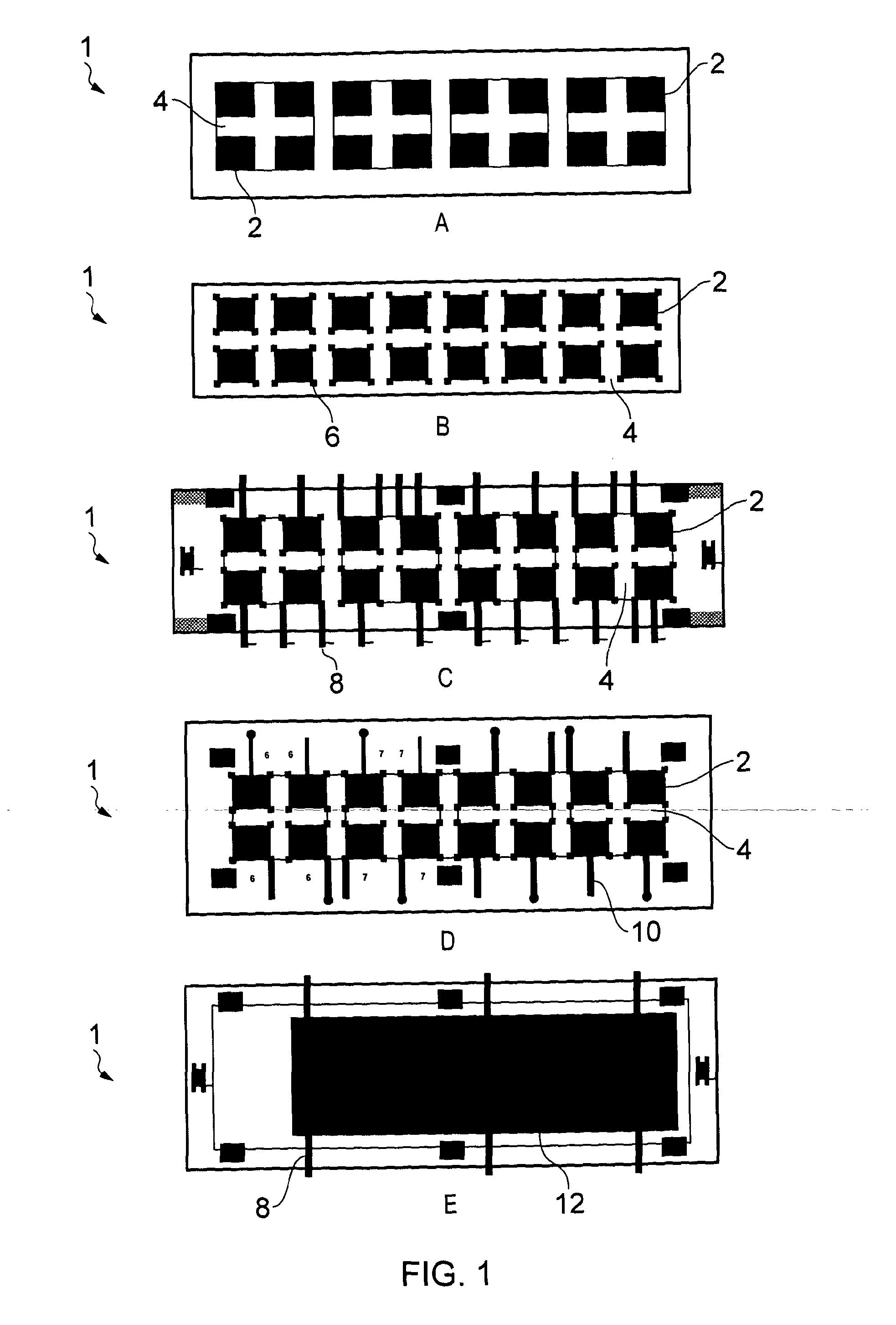
[0135]As many array sample liquids, include surfactant, providing a sample solution containing surfactant was investigated. Satisfactory sample spreading was observed for 8 μl of dye solution in PBS with 0.05% Tween, with side loading from a pipette into a hydrophilic channel, as shown in FIG. 6A. The second surface was a Menzel-Glaser slide (no array), with a 200 μm gap between the first and second surfaces. The hydrophobic boundaries were formed from CYTOP. FIG. 6B illustrates sample loading where a groove is provided. Satisfactory sample spreading is shown in FIG. 6B. The liquid is water soluble dye in PBS buffer. The hydrophobic boundaries were formed from parylene.

[0136]FIG. 6C shows improved filling to the corners of the hydrophilic surface when an overflow region is provided.

example 2

ffusion

[0137]In order to assess the diffusion of analytes in a liquid sample held between the first and second surfaces, a sample solution comprising fluorescently labelled BSA-AlexaFluor647 (1:1000 solution in PBS of 2 mg / ml stock of labelled protein) was loaded onto an example assembly. The non-specifically protein adsorbant surface (second surface; no array) used in these tests was home-made nitrocellulose spincoated onto silanated glass.

[0138]The surface was allowed to bind the protein for 30 min at room temperature, after which the second surface was rinsed by dipping quickly in abundant amount of PBS for 5 minutes with gentle shaking, dried and imaged on a fluorescent microarray scanner.

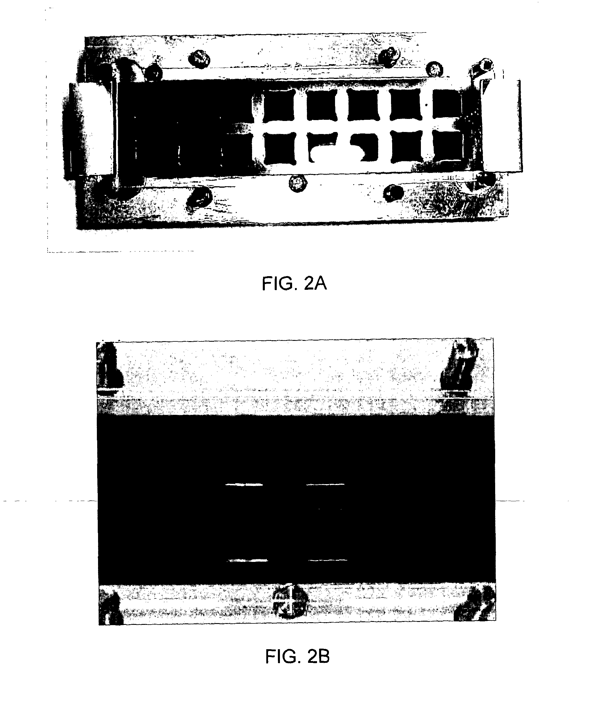
[0139]The data demonstrate that not only physical filling of the virtual ‘wells’ of the desired shape is possible, but also that fluorescently labelled BSA diffuses towards the ‘array’ surface throughout our quasi-square shape hydrophilic region in a reasonably uniform fashion. This is shown in...

example 3

Assay

[0142]A reverse-phase microarray assay, where BSA as a binding agent interacts with the probe rabbit anti-BSA serum, was chosen as a model to demonstrate the efficacy of the invention, where a planar microarray is used. Two types of arrayed patterns of BSA were used: a 10×10 array created as 16 pads spaced at 9 mm and a pattern covering nearly the whole slide solidly, generated by 4 arrayer tips, both with spot-to-spot spacing of 500 μm. BSA was spotted in PBS at 1 nl volume on Perkin Elmer Piezorray™. The blocker was β-lactoglobulin (BLG). The arrays were probed in the first reaction with rabbit anti-BSA serum followed by a wash. In the second reaction, binding was detected with anti-rabbit AlexaFluor647.

[0143]The reactions were then incubated for the desired length of time, which was one hour for the anti-BSA in the first reaction and 45 minutes for fluorescently labelled antibodies in the second reaction. Each of the 2 steps of binding reactions were done inside a humidity c...


PUM

PropertyMeasurementUnit
volumeaaaaaaaaaa
volumeaaaaaaaaaa
volumeaaaaaaaaaa

Abstract

The present invention relates to assay assemblies, components of assay assemblies, methods of determining one or more properties of a sample liquid, and methods of making components of assay assemblies. The present invention allows the properties of very small volumes of sample liquid to be probed, by providing a first surface having at least one sample liquid wettable surface region defined by a sample liquid repelling boundary, and a second surface, opposed to the first surface, having analyte binding agent immobilised thereon.

Description

FIELD OF THE INVENTION [0001]The present invention relates to assay assemblies, to kits comprising components of assay assemblies, to methods of determining one or more properties of a sample liquid, and to methods of making components of assay assemblies.BACKGROUND OF THE INVENTION[0002]Assay systems employing immobilised binding agents are a valuable tool in probing liquid samples.[0003]Of particular interest are microarrays. (As used herein, the term “microarray” is intended to include nano-arrays. It will be understood that the term typically also includes mesoarrays.) Typically, two-dimensional microarrays are formed on substrates which have analyte binding agents immobilised on the substrate surface. Suitable analyte binding agents include proteins / peptides, nucleic acid molecules, lipids, viruses, tissues and cells. In microarray technology, the immobilised binding agents are provided on the surface of the substrate in discrete array elements (e.g. spots). The functionalised ...

Claims


Application Information

Patent Timeline
Patent Type & Authority Applications(United States)
IPC IPC(8): G01N33/53
CPCB01L3/5085G01N33/5306B01L2200/0605B01L2200/0642B01L2300/0636B01L2300/0819B01L2300/0822B01L2300/16B01L2400/0406G01N33/54366B01J2219/00619B01J2219/00635B01J2219/00637B01J2219/00659B01L3/5088B01J19/00B01L3/00G01N33/543
Inventor MCKENNA, EKATERINA OLEGOVNALI, YIFANPITT, ANDREW ROBERTWALTON, ANTHONY JOHNPARKES, WILLIAM
Owner MCKENNA EKATERINA OLEGOVNA
Learn More