
Effusion cooled shroud segment with an abradable system

Active Publication Date: 2013-10-03
ROLLS ROYCE PLC
View PDF8 Cites 9 Cited by
  • Summary
  • Abstract
  • Description
  • Claims
  • Application Information

AI Technical Summary

Benefits of technology

The patent text describes a design feature for a seal segment that helps prevent abraded material from blocking the effusion ducts. This feature is achieved through the use of grooves in the abradable layer. The relatively large cross-section of these grooves provides space for the abraded material to collect without obstructing the ducts. This allows for proper gas washing of the seal segment surface. Overall, this design feature improves the efficiency and durability of the seal segment.

Problems solved by technology

However as turbine entry temperatures increase, the life of an un-cooled turbine falls, necessitating the development of better materials and the introduction of internal air cooling.
The cooling air from the compressor that is used to cool the hot turbine components is not used fully to extract work from the turbine.
Therefore, as extracting coolant flow has an adverse effect on the engine operating efficiency, it is important to use the cooling air effectively.
As the disc and the blades of the turbine rotate, they are subject to considerable centrifugal force and temperatures.
The centrifugal force and high temperature cause the turbine to extend in the radial direction and this can cause “rubbing” as the tips of the blades come into contact with the seal segments.

Method used


Image

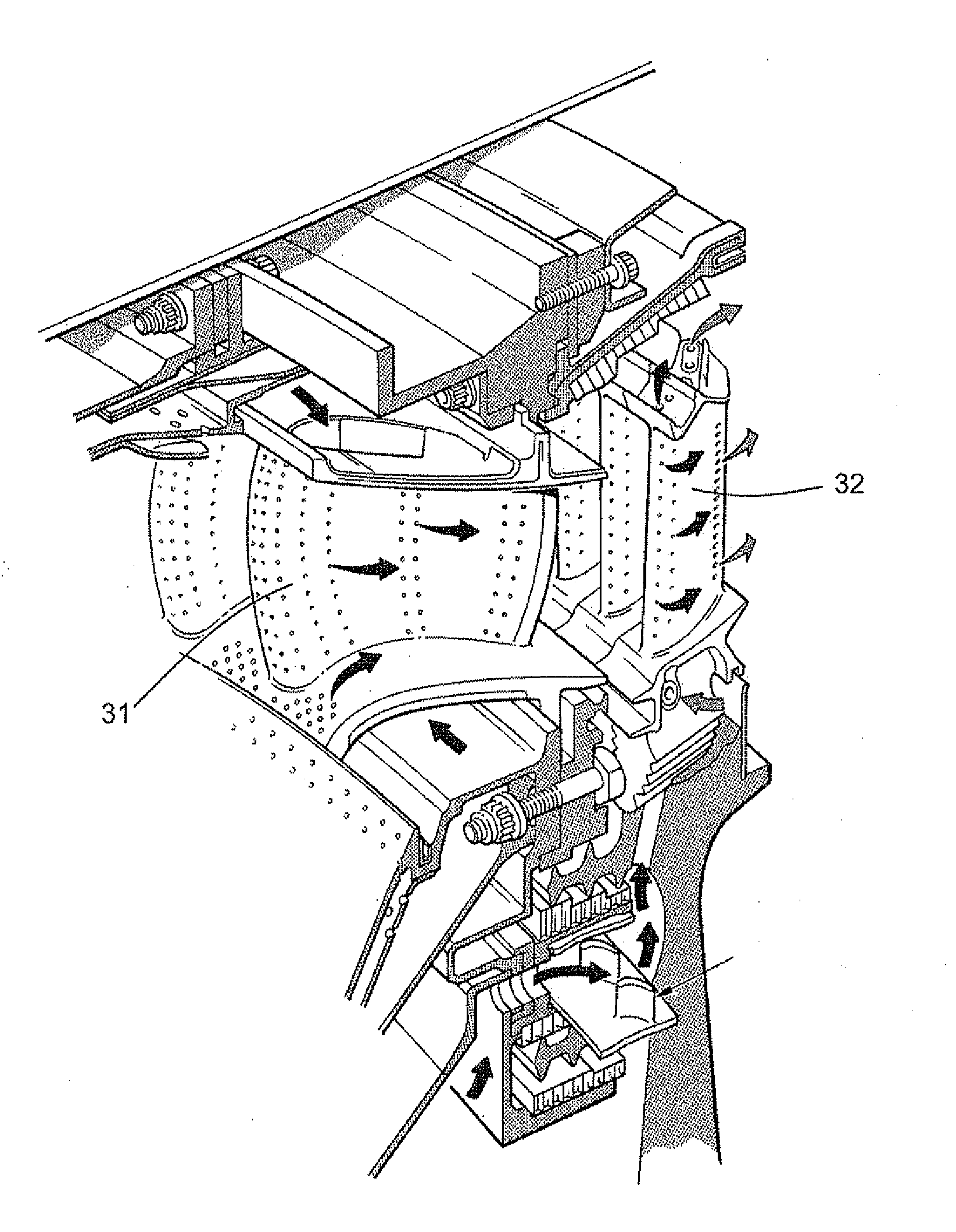
  • Effusion cooled shroud segment with an abradable system
  • Effusion cooled shroud segment with an abradable system
  • Effusion cooled shroud segment with an abradable system

Examples


Embodiment Construction

[0041]FIG. 3 shows a side elevation of a seal segment 40 of a seal segment ring of a gas turbine in accordance with an embodiment of the present invention. A bond interlayer 42 bonds an abradable coating layer 44 to the radially inner surface of the seal segment 40. The seal segment ring surrounds the tips of turbine blades 46, which rotate within the seal segment 40 assembly.

[0042]Coolant is effused 48 from the outboard side 50 of the seal segment 40 through a series of effusion ducts 52, which extend through the seal segment 40, bond interlayer 42 and abradable coating 44 towards the turbine blades 46. The effusion ducts 52 open into one or more grooves 54, which are provided in the inboard surface of the abradable coating 44. The grooves 54 are longitudinal and extend circumferentially around the seal segment so as to form annular grooves 54. The grooves 54 lie in a parallel orientation relative to one another and to the edge of the circumferential edge of the segment. The dimens...


PUM

PropertyMeasurementUnit
Angleaaaaaaaaaa
Angleaaaaaaaaaa
Angleaaaaaaaaaa

Abstract

A turbine casing assembly, comprising an annular seal segment assembly for surrounding the turbine adjacent to the turbine blades. An abradable coating is provided on the inboard surface of the seal segments of the assembly and one or more coolant ducts extend from the outboard surface of the seal segment assembly through respective seal segments and the abradable coating, for carrying a coolant towards the blade tips. One or more annular grooves are formed in the inboard surface of the abradable coating, the or each coolant duct opening into one of the one or more annular grooves.

Description

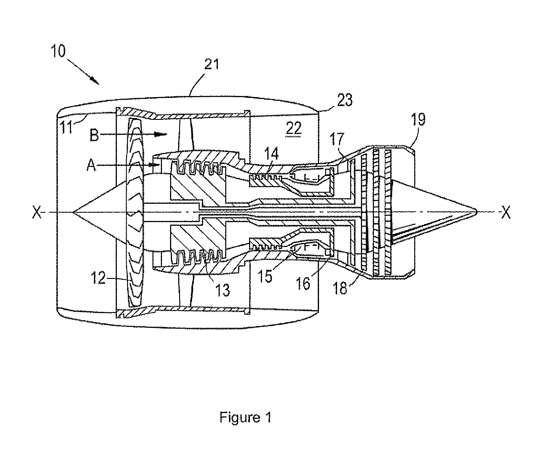
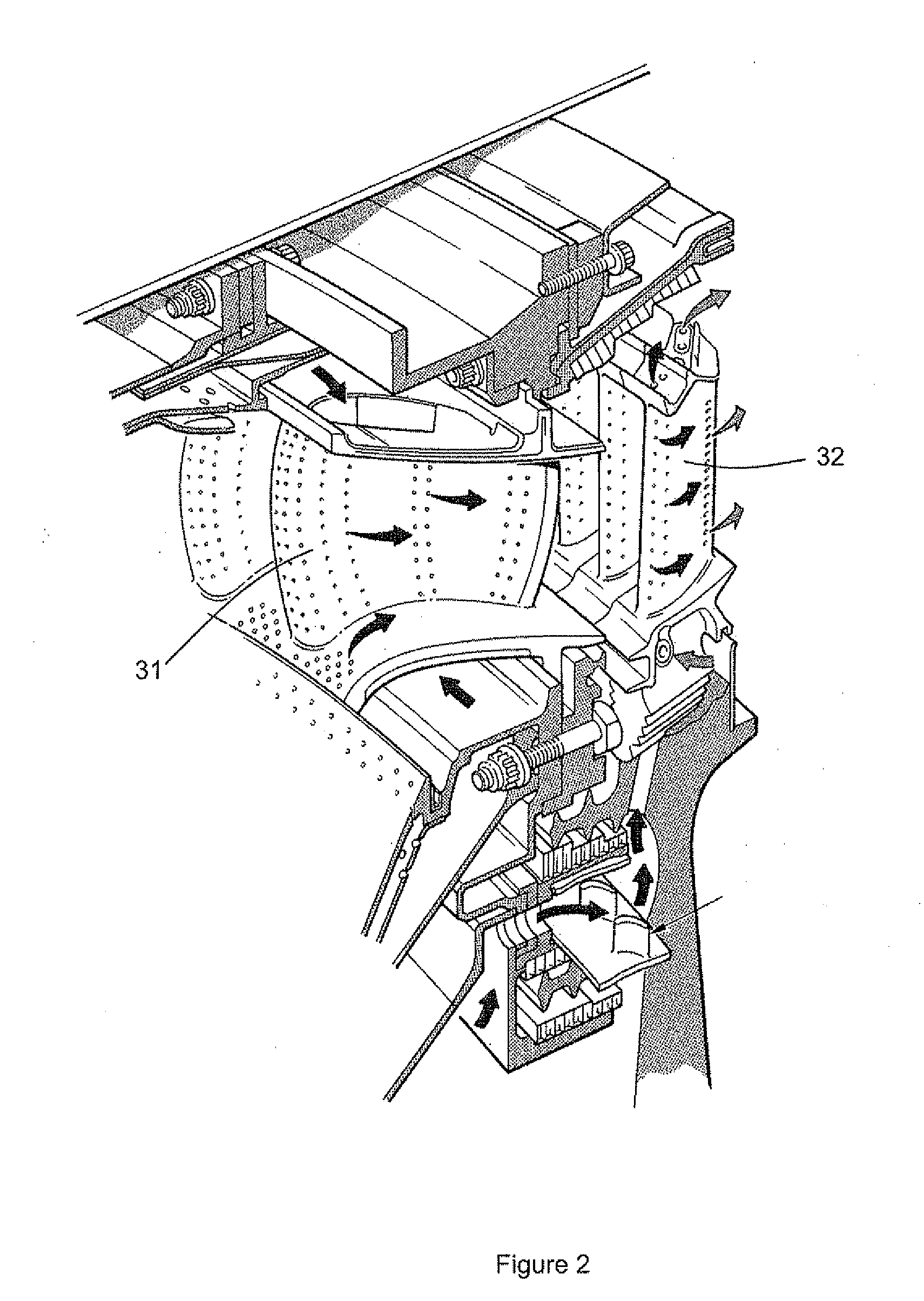
FIELD OF THE INVENTION[0001]The present invention relates to effusion cooling of seal segments within a gas turbine engine.BACKGROUND OF THE INVENTION[0002]Modern gas turbine engines, and more specifically turbofans for use in aviation, provide power by compressing air using a compressor, adding fuel to this compressed air, combusting this mixture such that it expands through the blades of a turbine and exhausting the produced gases.[0003]With reference to FIG. 1, a ducted fan gas turbine engine generally indicated at 10 has a principal and rotational axis X-X. The engine comprises, in axial flow series, an air intake 11, a propulsive fan 12, an intermediate pressure compressor 13, a high-pressure compressor 14, combustion equipment 15, a high-pressure turbine 16, and intermediate pressure turbine 17, a low-pressure turbine 18 and a core engine exhaust nozzle 19. A nacelle 21 generally surrounds the engine 10 and defines the intake 11, a bypass duct 22 and a bypass exhaust nozzle 23...

Claims


Application Information

Patent Timeline
IPC IPC(8): F02C7/12
CPCF02C7/12F01D11/122F05D2300/134F05D2240/11F05D2230/90
Inventor RAZZELL, ANTHONY GORDONHARDING, ADRIAN LEWIS
Owner ROLLS ROYCE PLC
Features
  • Generate Ideas
  • Intellectual Property
  • Life Sciences
  • Materials
  • Tech Scout
  • Unparalleled Data Quality
  • Higher Quality Content
  • 60% Fewer Hallucinations
Learn More