Hydrogen Sensor and Method of Manufacturing the Same

a technology of hydrogen sensors and sensors, which is applied in the direction of instruments, vacuum evaporation coatings, specific gravity measurements, etc., can solve the problems of high operating temperature, no selectivity, and easy explosion of hydrogen gas in the actual li

Active Publication Date: 2013-10-03
IND ACADEMIC CORP FOUND YONSEI UNIV
View PDF13 Cites 6 Cited by
  • Summary
  • Abstract
  • Description
  • Claims
  • Application Information

AI Technical Summary

Benefits of technology

[0044]According to embodiments of the present invention, hydrogen sensors having nanogaps can be mass-produced by a method different from a traditional method.

Problems solved by technology

However, since there is a danger in that hydrogen gas is vulnerable to explosion when it leaks into the surrounding atmosphere at a concentration of 4% or more, application in actual life is difficult unless the safety of use is guaranteed.
However, the ceramic/semiconductor sensors cannot detect high concentrations of hydrogen gas, since they are saturated in high concentrations of hydrogen gas, which is problematic.
However, this sensor requires a high operating temperature and has no selectivity, which is problematic.
However, these sensors have a drawback in that, for example, the ability degrades when the sensors are repeatedly exposed to high concentrations of hydrogen gas.
Although these sensors have an ability to detect various types of gases, they suffer from the disadvantage whereby the methods of manufacturing the sensors are complicated and difficult.
However, despite the respective advantages of these technologies, the performance of these sensors is still dissatisfactory in terms of the initial concentration of hydrogen gas that can be detected, response time, detection temperature, drive voltage and the like, which can be regarded as key factors of a hydrogen sensor.
However, the disadvantages are that the method of manufacturing the sensor is complicated and the minimum concentration that can be detected is high.
In addition, in the case in which the Pd particles are not bonded to the substrate, if the exposure to hydrogen is stopped after the Pd lat

Method used


Image

  • Hydrogen Sensor and Method of Manufacturing the Same
  • Hydrogen Sensor and Method of Manufacturing the Same
  • Hydrogen Sensor and Method of Manufacturing the Same

Examples


Embodiment Construction

[0057]Reference will now be made in detail to various embodiments of the present invention, examples of which are illustrated in the accompanying drawings. In the following, descriptions of technical parts that are well known in the art will be omitted. Although such descriptions are omitted, the characteristic features of the present invention will be apparent to a person having ordinary skill in the art from the following description taken in conjunction with the accompanying drawings.

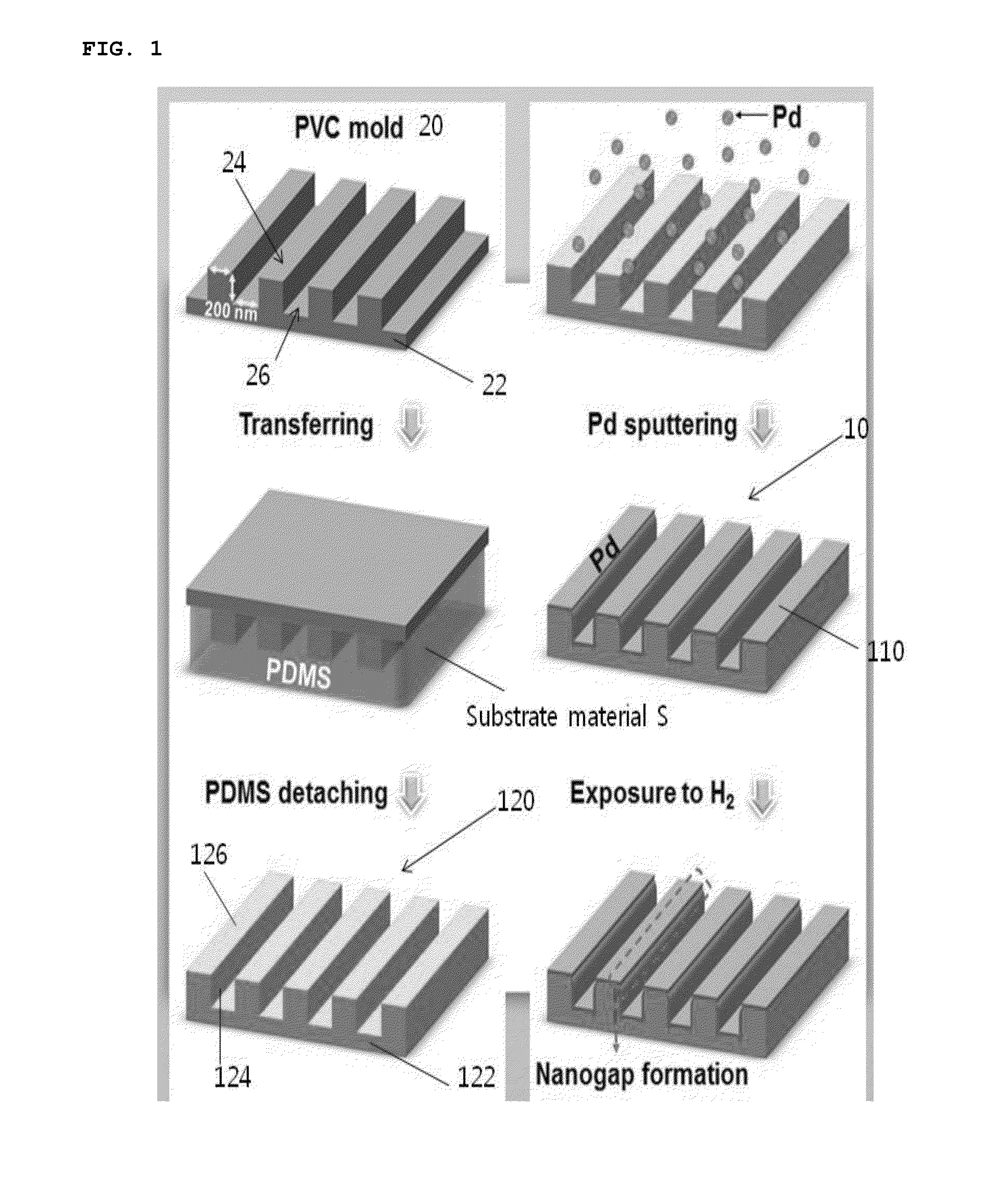
[0058]FIG. 1 schematically shows a process of manufacturing a hydrogen sensor according to an embodiment of the present invention.

[0059]As shown in FIG. 1, according to an embodiment of the present invention, a hydrogen sensor is manufactured using nanoimprinting technology. Specifically, a mold 20 having a pattern corresponding to nanogaps that are to be formed in a hydrogen sensor substrate is prepared. According to an embodiment of the present invention, the mold 20 that is employed is a PVC mold ...


PUM

PropertyMeasurementUnit
Thicknessaaaaaaaaaa
Thicknessaaaaaaaaaa
Flexibilityaaaaaaaaaa

Abstract

A method of the invention includes preparing a mold having a hydrogen detection part pattern, a nanogap pattern and a base to be formed on a hydrogen sensor substrate; preparing a material to which the patterns are transferrable; forming the hydrogen sensor substrate by bringing the mold into contact with the material to thus transfer the patterns to the material and then detaching the mold from the material to which the patterns are transferred, the hydrogen sensor substrate having a base part corresponding to the base, a plurality of hydrogen detection parts erected from the base part and corresponding to the nanogap pattern and a plurality of nanogaps formed between the hydrogen detection parts and corresponding to the hydrogen detection part pattern; and forming, on the hydrogen sensor substrate, a thin film of a transition metal or an alloy thereof to be expanded by hydrogen.

Description

CROSS REFERENCE TO RELATED APPLICATION[0001]The present application claims priority from Korean Patent Application Number 10-2012-0027626 filed on Mar. 19, 2012, the entire contents of which application are incorporated herein for all purposes by this reference.BACKGROUND OF THE INVENTION[0002]1. Field of the Invention[0003]The present invention relates to a method of manufacturing a hydrogen sensor, and more particularly, to a hydrogen sensor and a method of manufacturing the same, in which a thin film made of a transition metal or an alloy thereof is used.[0004]2. Description of Related Art[0005]Active studies on hydrogen energy are underway since the hydrogen energy has merits in that it is renewable and does not create environmental pollution.[0006]However, since there is a danger in that hydrogen gas is vulnerable to explosion when it leaks into the surrounding atmosphere at a concentration of 4% or more, application in actual life is difficult unless the safety of use is guara...

Claims


Application Information

Patent Timeline
IPC IPC(8): G01N33/00C23C30/00
CPCG01N33/0036C23C30/00G01N33/005G01N27/128C23C14/205G01N27/12
Inventor LEE, WOO YOUNGLEE, HEONCHANG, BYUENG JINLEE, SEUNG HYUNLEE, JUN MIN
Owner IND ACADEMIC CORP FOUND YONSEI UNIV
Why Eureka
Try Eureka