Exhaust gas treatment system

Active Publication Date: 2013-10-03
MITSUBISHI HEAVY IND ENG LTD
View PDF0 Cites 7 Cited by
  • Summary
  • Abstract
  • Description
  • Claims
  • Application Information

AI Technical Summary

Benefits of technology

[0016]According to the present invention, the heat recovered from exhaust gas is used for CO2 removal process. This makes it possible to enhance the thermal efficiency in the exhaust gas treatment apparatus. Using the heat r

Problems solved by technology

In the step of regenerating the absorbing solution in p

Method used


Image

  • Exhaust gas treatment system
  • Exhaust gas treatment system
  • Exhaust gas treatment system

Examples


first embodiment

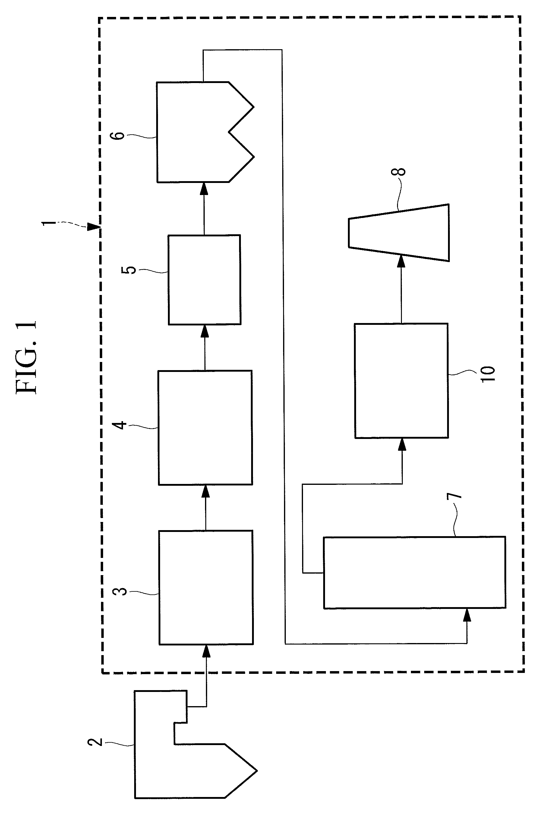
[0021]FIG. 1 is a schematic view of an exhaust gas treatment system. The exhaust gas treatment system 1 is placed on a gas downstream side of a combustion facility such as a boiler 2. Arrows in the drawing indicate the flow of exhaust gas generated in the boiler 2. The exhaust gas treatment system 1 includes, in order from the gas upstream side, a NOx removal unit 3, an air heater 4, a dry electrostatic precipitator 6, a wet desulfurization unit 7, a CO2 recovery unit 10, and a smokestack 8. In the exhaust gas treatment system 1 of the first embodiment, an exhaust gas heat exchanger 5 is placed between the air heater 4 and the dry electrostatic precipitator 6. The exhaust gas heat exchanger 5 may be placed between the dry electrostatic precipitator 6 and the wet desulfurization unit 7.

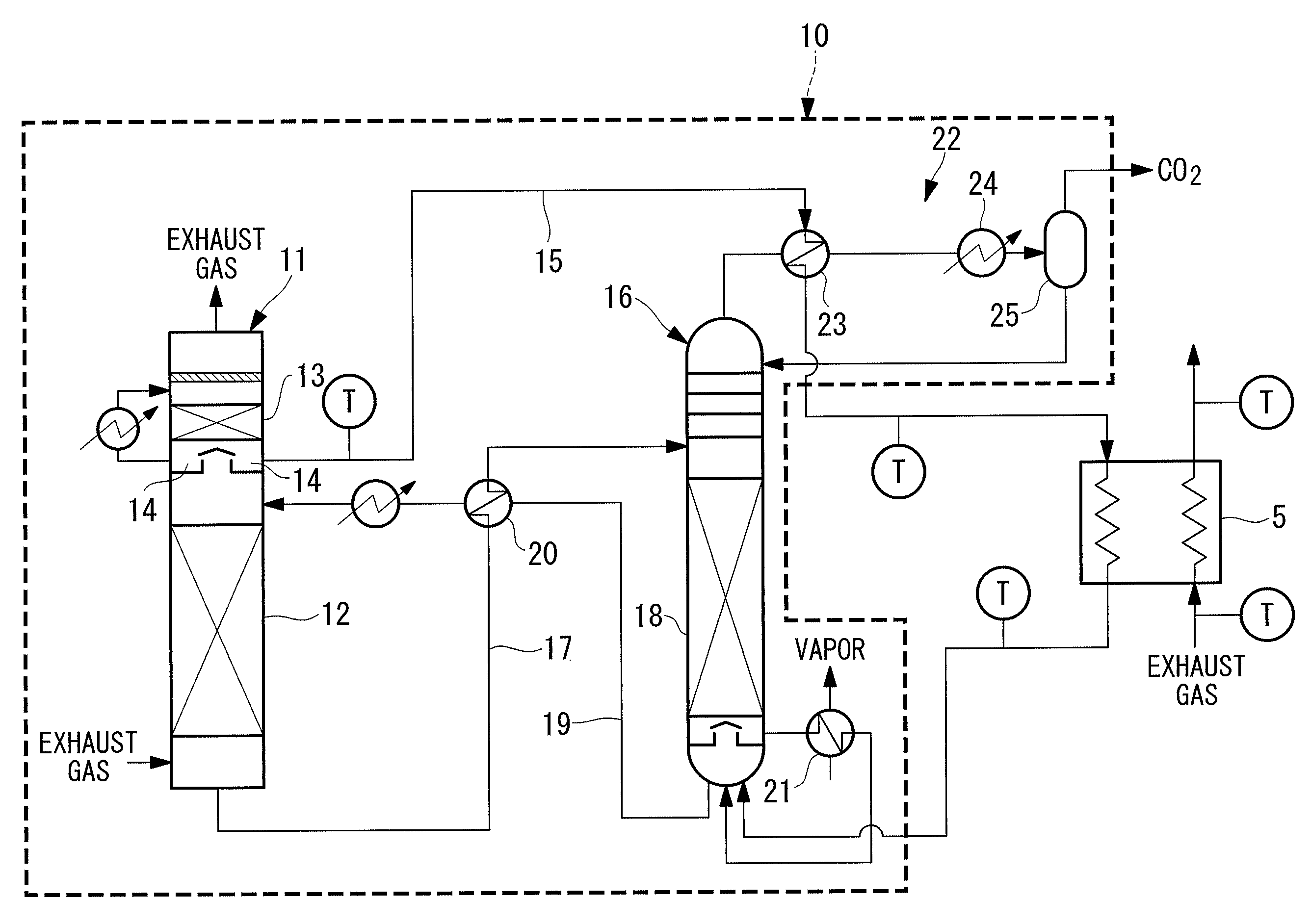
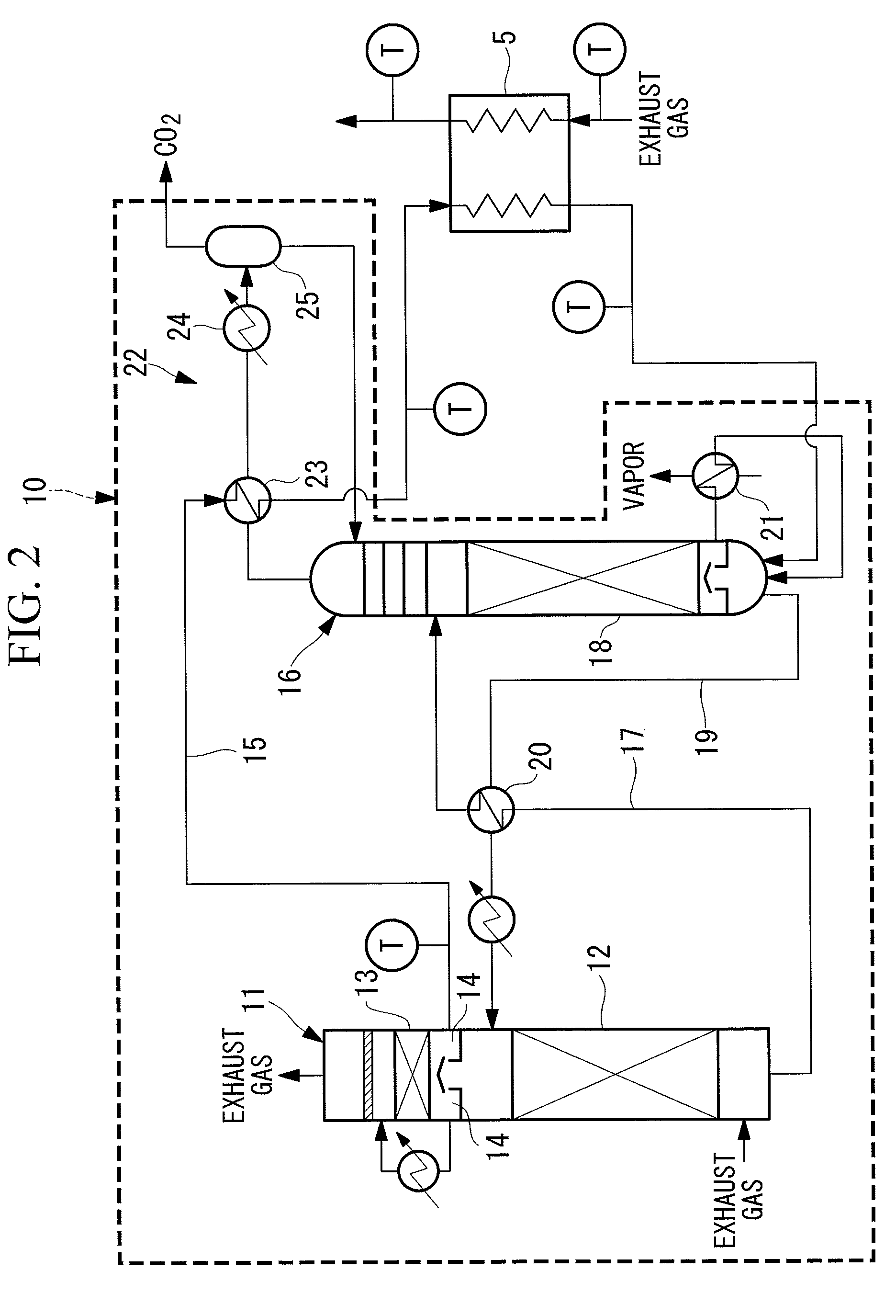
[0022]FIG. 2 is a schematic view for explaining the CO2 recovery unit in the exhaust gas treatment system according to the first embodiment. The CO2 recovery unit 10 in the first embodiment includes a ...

second embodiment

[0042]FIG. 3 is a schematic view for explaining a CO2 recovery unit in an exhaust gas treatment system according to a second embodiment. In FIG. 3, structure components identical to those in FIG. 2 are designated by identical reference signs. The overall structure of the exhaust gas treatment system is identical to that of FIG. 1.

[0043]Water vapor generated in the boiler is used in a power generation facility such as a turbine and is then cooled. In the exhaust gas treatment system of the second embodiment, a boiler feed water pipeline 31 is placed so that the cooled boiler feed water circulates to the boiler via a heat exchanger 33 of a CO2 separation section 32 and an exhaust gas heat exchanger 34.

[0044]In a CO2 recovery unit 30 of FIG. 3, a pipeline which connects the top portion of the absorbing solution regeneration column 16 and the separation drum 25 branches to two lines. One line extends from the absorbing solution regeneration column 16 to the separation drum 25 via the he...

example 1

[0050]The amount of heat required for the reboiler in the case of treating exhaust gas with use of the exhaust gas treatment system including the CO2 recovery unit shown in FIG. 2 was calculated. In calculation, the temperatures of the condensate and the exhaust gas were set as shown in Table 1. The flow rate of the condensate was set at 11.2 ton / hr and the pressure of the condensate at an inlet port of the exhaust gas heat exchanger was set at 6 atm.

TABLE 1Exhaust gasCondensate temperature (° C.)temperature (° C.)ExhaustExhaustExhaustHeatHeatgas heatgas heatgas heatexchangerexchangerexchangerexchangerexchangerinlet portoutlet portoutlet portinlet portoutlet portCase 1498215617790Case 2498213914990Case 3498212713590


PUM


Abstract

There is provided an exhaust gas treatment system including a CO2 recovery unit with further enhanced energy efficiency. The exhaust gas treatment system (1) includes: a CO2 recovery unit (10) including a CO2 absorption column (11), an absorbing solution regeneration column (16), a condensate supply pipeline (15) for supplying condensate, which contains CO2 absorbing solution discharged from the CO2 absorption column (11) to a bottom portion of the absorbing solution regeneration column (16), and a CO2 separation section (22) for performing heat exchange, via a heat exchanger (23), between the CO2 discharged from the absorbing solution regeneration column (16) and the condensate; and an exhaust gas heat exchanger (5) provided on a gas upstream side of the CO2 recovery unit (10) for performing heat exchange between exhaust gas before flowing into the CO2 recovery unit (10) and the condensate.

Description

TECHNICAL FIELD[0001]The present invention relates to an exhaust gas treatment system having a carbon dioxide (CO2) recovery unit placed for removing CO2 from exhaust gas.BACKGROUND ART[0002]In thermal power systems for generating power by combusting fossil fuels such as coal and heavy fuel, a large amount of CO2 is discharged. In recent years, the greenhouse effect by CO2 is pointed out as one of the causes of the global warming. It is necessary, therefore, to take prompt measures to protect the global environment on an international basis. Under these circumstances, there is a trend toward further increase in demand for CO2 discharge control.[0003]In the thermal power systems, there is installed an exhaust gas treatment system including a CO2 recovery unit placed in a flow passage on the downstream side of a boiler. The CO2 recovery unit includes a CO2 absorption column and a CO2 regeneration column as described in Patent Literature 1 and Patent Literature 2. In the CO2 absorption...

Claims


Application Information

Patent Timeline
IPC IPC(8): B01D53/18C01B32/50
CPCB01D53/1425B01D53/1475F23J15/04F23J2219/40Y02C10/06Y02C10/04F23J2215/50B01D2258/0283Y02C20/40Y02E20/32
Inventor TSUJIUCHI, TATSUYAHONJO, SHINTAROYONEKAWA, TAKAHITOSUGITA, SATORUITO, MOTOFUMIKAMIJO, TAKASHINAGAYASU, TATSUTOOKAMOTO, TAKUYA
Owner MITSUBISHI HEAVY IND ENG LTD
Why Eureka
Try Eureka