

Uniform Crimping and Deployment Methods for Polymer Scaffold
a polymer scaffold and uniform crimping technology, applied in the field of drugeluting medical devices, can solve the problems of ring struts and/or cell structures, unable to consistently expand in a uniform manner, early crimping processes, etc., and achieve the effect of increasing the uniformity of polymer scaffold expansion
- Summary
- Abstract
- Description
- Claims
- Application Information
AI Technical Summary
Benefits of technology
Problems solved by technology
Method used
Image

Examples
example 1
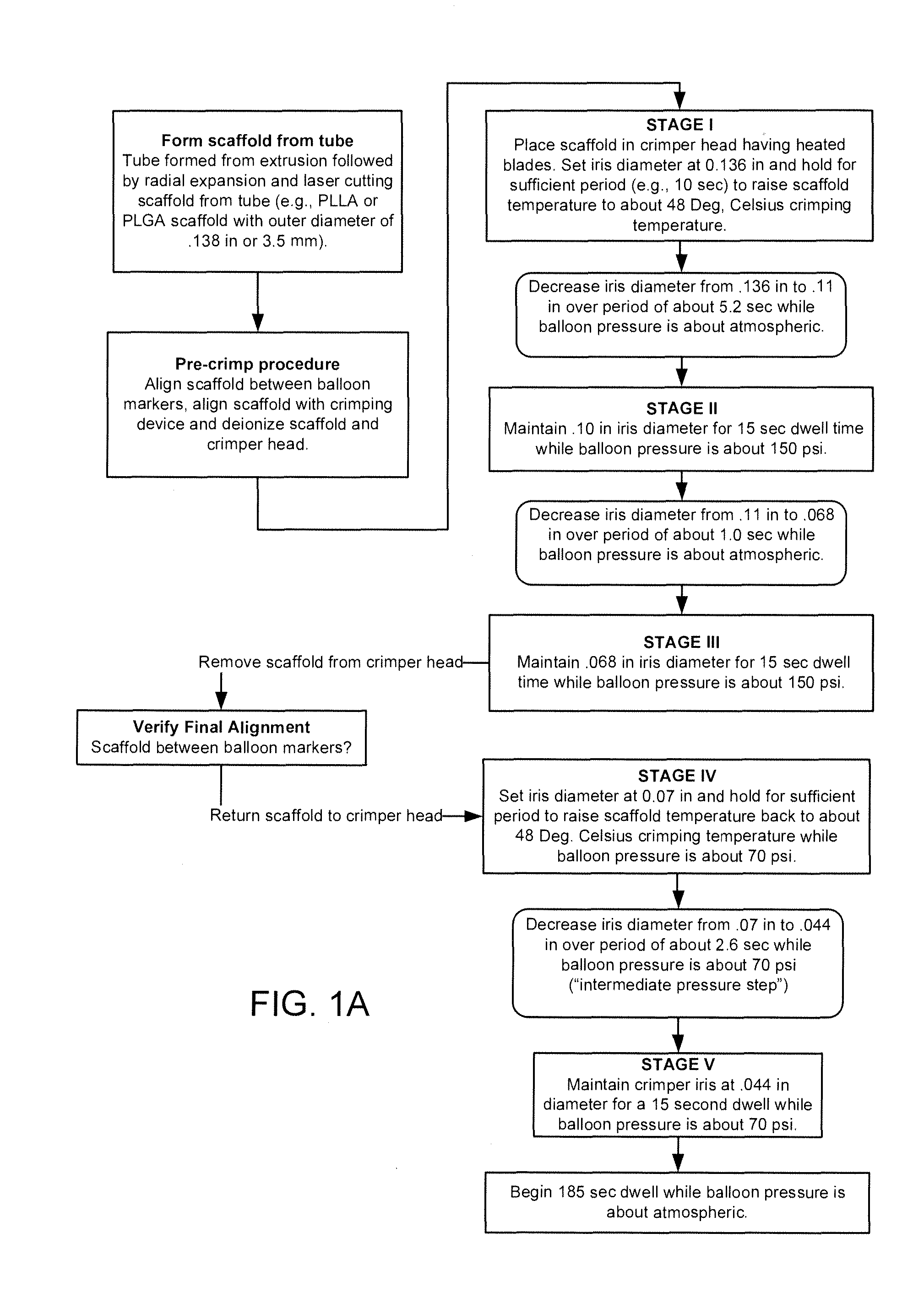
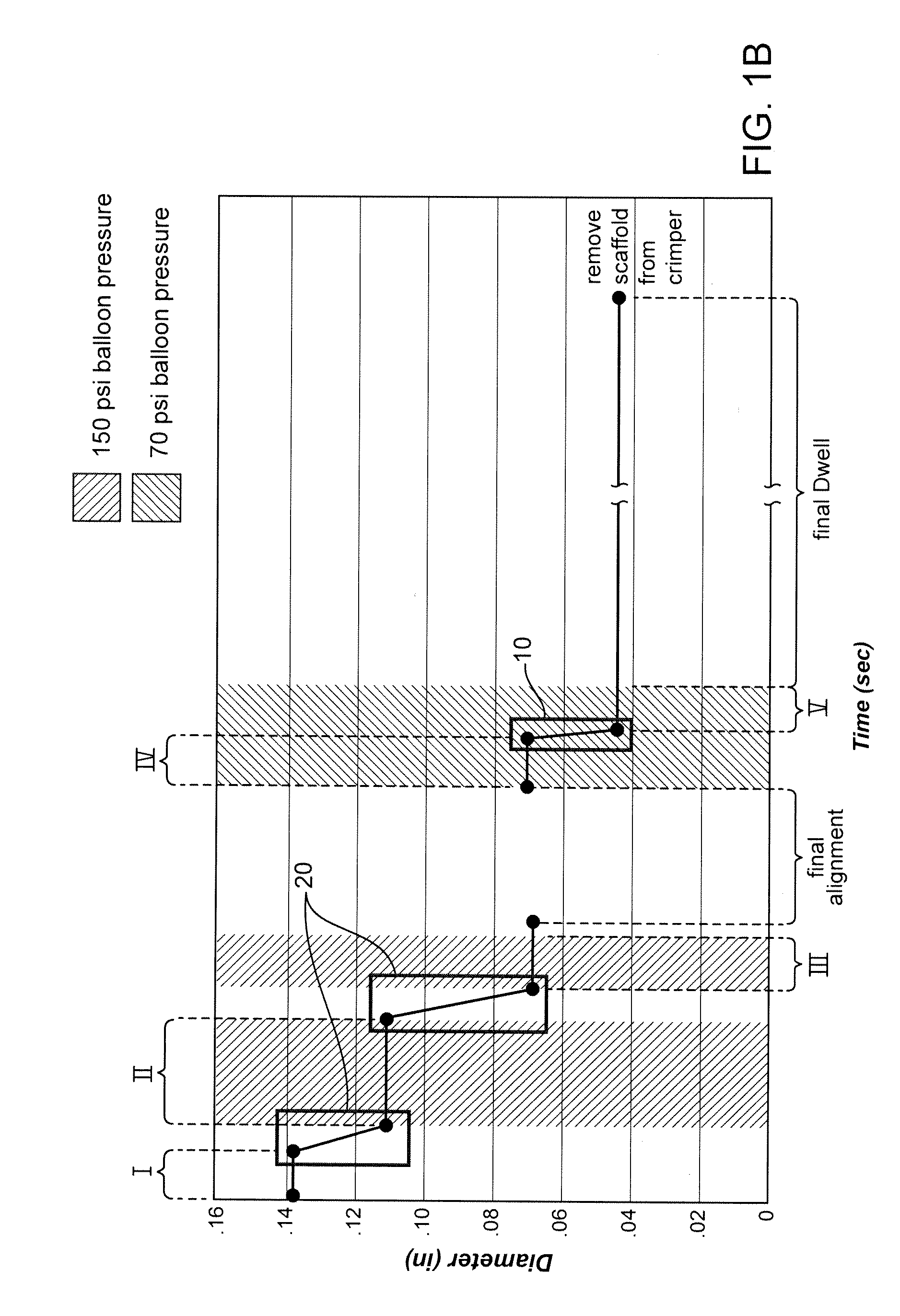
[0077]Further details of the FIG. 1A flow process for a 3.5 mm scaffold manufacture and crimping to a delivery balloon will now be discussed. FIG. 1B illustrates in graphical form the crimping portion of the FIG. 1A flow—a graph of scaffold diameter verses time with a balloon pressure of 150 psi or 70 psi applied during the dwell periods and the intermediate pressure step (i.e., crimping between Stage IV and Stage V). The scaffold was crimped using a crimper having film-sheets disposed between the metal crimper blades and the scaffold. This particular type of crimper was discussed earlier in connection with FIGS. 8A-8B.
[0078]As discussed above, the scaffold is formed from a PLLA or PLGA precursor, including a biaxial expansion of the precursor to form a tube, followed by laser cutting the scaffold from the tube. Next, a pre-crimp procedure is performed, which includes placing the scaffold between the balloon markers and aligning the scaffold with the iris of the crimper. Using an an...
example 2
[0100]The process described in FIGS. 1A-1B had been adopted in a modified form for use in crimping a scaffold intended for use in a peripheral artery, e.g., a scaffold described in co-pending application Ser. No. 13 / 015,474 (docket no. 104584.10). When applied to this peripheral scaffold, however, it was found that the scaffold exhibited non-uniform expansion characteristics. In order to address this problem, a modified crimping process was devised. Such a process is described in co-pending application Ser. No. 13 / 194,162(docket no. 104584.19) ('162 application), which has a common assignee to the present application. The process proposed is summarized in TABLE 1.
TABLE 1Crimping process described in the ′162 applicationOuterCrimpBalloonCrimpDiameterheadDwellBalloonpressurizationControlsettingSpeedtimespressurizationdwell timessettings(in.)(in / sec)(sec)(50 psi)(sec)Initial0.640pointStep 10.3540.3000Ambient0Step 20.2700.00530Ambient0Step 30.2100.00530Ambient0Step 40.1600.00530Ambient0...
example 3
[0111]FIGS. 4A-4B illustrate the steps associated with a first example of a crimping process according to the preferred embodiments. FIG. 4B illustrates in graphical form the crimping portion of the FIG. 4A flow—a graph of scaffold diameter verses time with a balloon pressure of between about 20-70 psi applied throughout substantially all of the crimping process. For example, the balloon pressure is maintained at between 20-70 psi until the completion of a Stage IV of a preferred crimping process.
[0112]Stage I:
[0113]The scaffold supported on the inflated balloon of the balloon-catheter is placed within the crimp head. The balloon when inflated and supporting the scaffold in this state preferably has substantially all folds removed.
[0114]After the scaffold reaches the crimping temperature, the iris of the crimper closes to reduce the scaffold inner diameter (ID) is slightly less than the outer diameter (OD) of the pressurized balloon (e.g., from 0.136 in (3.5 mm) to about 0.12 in, or...
PUM
| Property | Measurement | Unit |
|---|---|---|
| Temperature | aaaaa | aaaaa |
| Fraction | aaaaa | aaaaa |
| Fraction | aaaaa | aaaaa |
Abstract
Description
Claims
Application Information