Hybrid energy conversion device

a technology of energy conversion device and piezoelectric power, which is applied in the direction of generator/motor, pv power plant, greenhouse gas reduction, etc., can solve the problems of inability to adapt to structure specified in the above patent is incapable of using mechanical energy, and 705,523 b2 may not be modified to accommodate other kinds of less expensive solar cells. , to achieve the effect of reducing the cost of solar energy collection, reducing the cost of th

Inactive Publication Date: 2013-10-03
UNIVERSITY OF BOLTON
View PDF13 Cites 19 Cited by
  • Summary
  • Abstract
  • Description
  • Claims
  • Application Information

AI Technical Summary

Benefits of technology

[0007]Such a hybrid structure could function to harvest energy from multiple renewable sources through a single multi-source energy capture system. This may lead to energy capture systems that collect energy more effectively, or are more cost effective, robust, lightweight or deployable than comparable single-source energy capture systems.

Problems solved by technology

The use of such a system would be limited by the availability of sunlight to certain periods of the day.
The structure specified in the above patent is incapable of using mechanical energy.
The hybrid structure described in U.S. Pat. No. 7,705,523 B2 may not be modified to accommodate other kinds of less expensive solar cells, such as organic solar cells or amorphous silicon solar cells.
The structure is also highly complex, featuring a hierarchical structure including tubules with radiating nano-rods.

Method used


Image

  • Hybrid energy conversion device
  • Hybrid energy conversion device
  • Hybrid energy conversion device

Examples


Embodiment Construction

[0039]In order that the invention may be more clearly understood, embodiments thereof will now be described, by way of example only, with reference to the accompanying drawings, of which:

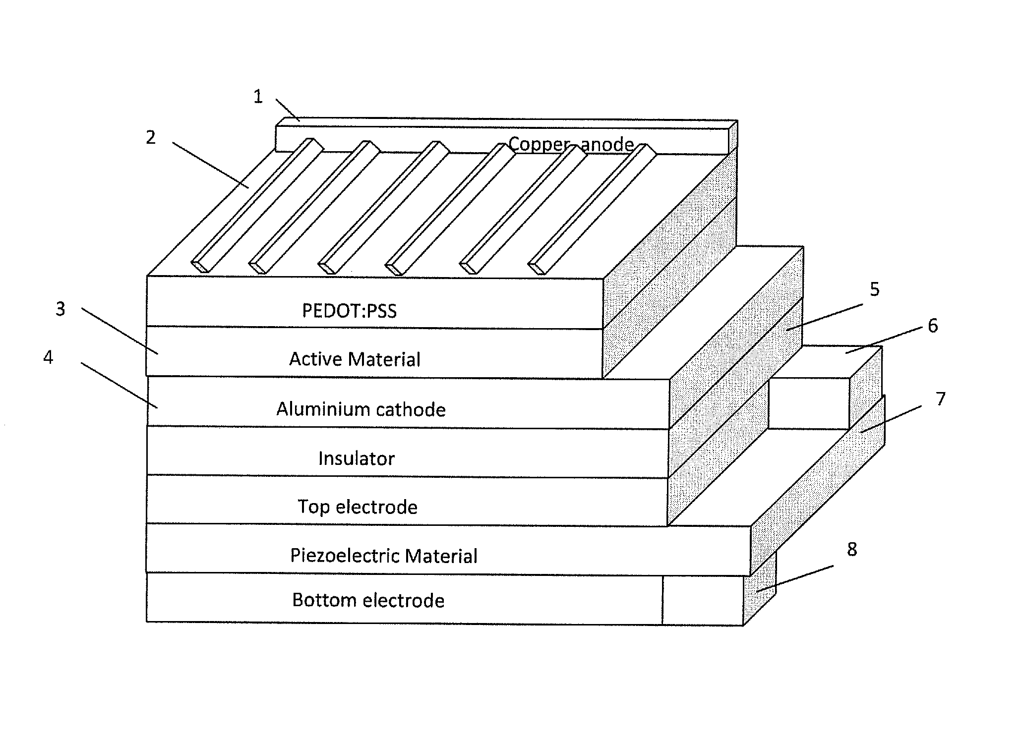
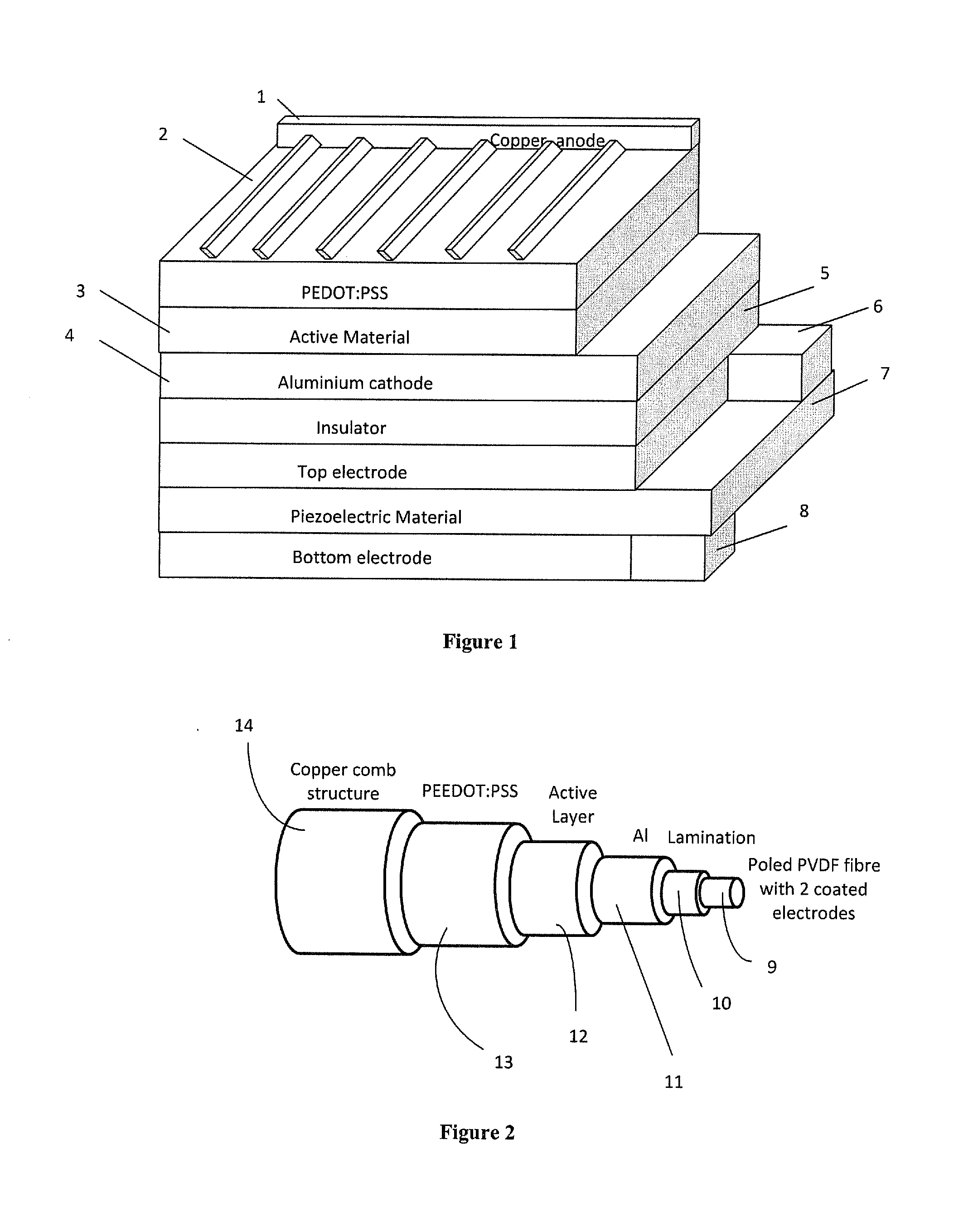
[0040]FIG. 1 is a perspective drawing of a section of a laminar piezoelectric-photovoltaic structure, such as a film, according to one embodiment of the present invention;

[0041]FIG. 2 is a perspective drawing of a section of a concentric piezoelectric-photovoltaic structure, such as a fibre, according to another embodiment of the present invention;

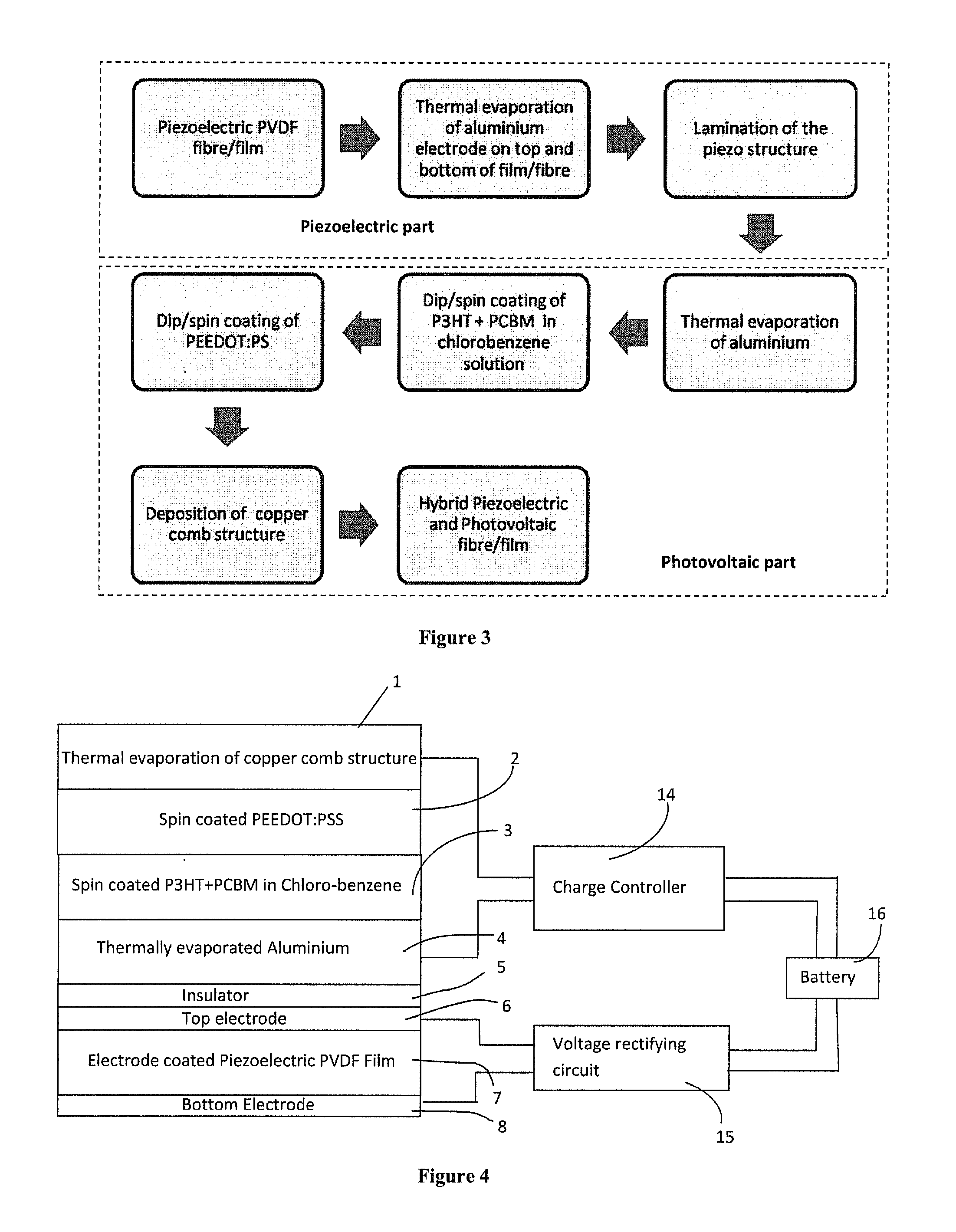
[0042]FIG. 3 is a flowchart showing a method for preparing the piezoelectric-photovoltaic structures of FIGS. 1 and 2;

[0043]FIG. 4 is a schematic of a power conversion system according to another embodiment of the present invention, which includes the piezoelectric-photovoltaic structure of FIG. 1;

[0044]FIG. 5 is a circuit diagram setting out a rectifier circuit suitable for use in the power conversion system of FIG. 4;

[0045]FIG. 6 is a schematic of an ene...


PUM

PropertyMeasurementUnit
thicknessaaaaaaaaaa
melting temperatureaaaaaaaaaa
thicknessaaaaaaaaaa

Abstract

A piezoelectric-photovoltaic hybrid structure is described, having a plurality of superposed layers including a photo voltaic layer and a piezoelectric substrate. A method of forming such a structure is also described, including the steps of providing a piezoelectric substrate and superposing a photovoltaic layer over the substrate. A power conversion system is described, comprising such a hybrid structure with a first circuit connected to the piezoelectric substrate and a second circuit connected to the photovoltaic layer. Also discussed is a method of generating, storing, distributing, or consuming electrical energy, involving the use of such a system in connection with a distribution circuit or network, electrical load, or energy storage device. A further power conversion system is described where the piezoelectric and photovoltaic circuits are connected to a single, or a respective, DC-DC converter. A set of such power conversion systems may be connected in series at their output terminals.

Description

TECHNICAL FIELD OF THE INVENTION[0001]The present invention relates to hybrid piezoelectric and photovoltaic materials and structures, and to power conversion systems and circuitry for such materials and structures.BACKGROUND TO THE INVENTION[0002]The availability of flexible photovoltaic and piezoelectric materials, coupled with increasing pressures to efficiently capture energy from renewable sources, makes the use of both piezoelectric and photovoltaic technologies, simultaneously and / or at the same location, an increasingly attractive possibility. A hybrid structure comprising both technologies may be deployed to harvest energy both from solar energy and from mechanical energy sources such as rain, wind, waves, or tides. A flexible piezoelectric polymer may be used to harvest mechanical energy and at the same time may act as a substrate material for organic photovoltaic cells.[0003]WO 2009 / 070706 describes the use of flexible organic solar cells for artificial turf to generate s...

Claims


Application Information

Patent Timeline
Patent Type & Authority Applications(United States)
IPC IPC(8): H01L31/058H02J1/12H02J7/34H02N2/18
CPCH01L27/301H02S10/10H01L31/0583H01L41/113H01L51/0036H01L51/0037H01L51/4253H02J1/10H02N2/181H02J1/12H02J7/345H02N2/186Y02E10/542H02S40/38H01L27/304Y02E10/52Y02E70/30H10N30/30H10K30/53H10K39/10H10K85/113H10K85/1135H10K30/30H01L31/056
Inventor SIORES, ELIASVATANSEVER, DERMANPREKAS, KLEANTHIS
Owner UNIVERSITY OF BOLTON
Why Eureka
Try Eureka