Method and system for performing on-wafer testing of heads

Inactive Publication Date: 2013-10-03
WESTERN DIGITAL TECH INC
View PDF8 Cites 152 Cited by
  • Summary
  • Abstract
  • Description
  • Claims
  • Application Information

AI Technical Summary

Problems solved by technology

Many of the tests desired to be performed for the heads 14 are destructive.
Once these destructive tests are performed in on-wafer testing, the heads 14 can no longer be placed in devices to be used and/or sold.
However, because the heads 14 have been heated above the blocking tem

Method used


Image

  • Method and system for performing on-wafer testing of heads
  • Method and system for performing on-wafer testing of heads
  • Method and system for performing on-wafer testing of heads

Examples


Embodiment Construction

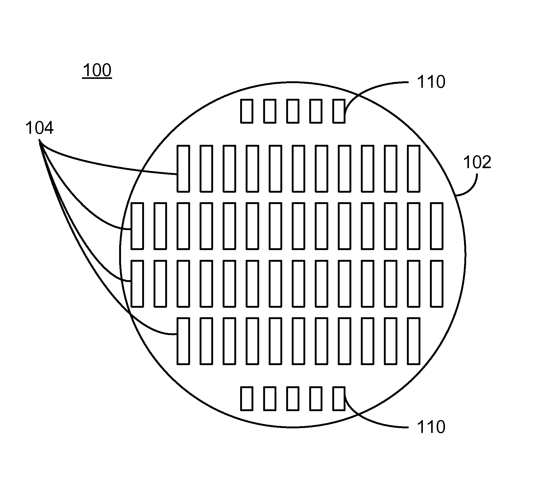
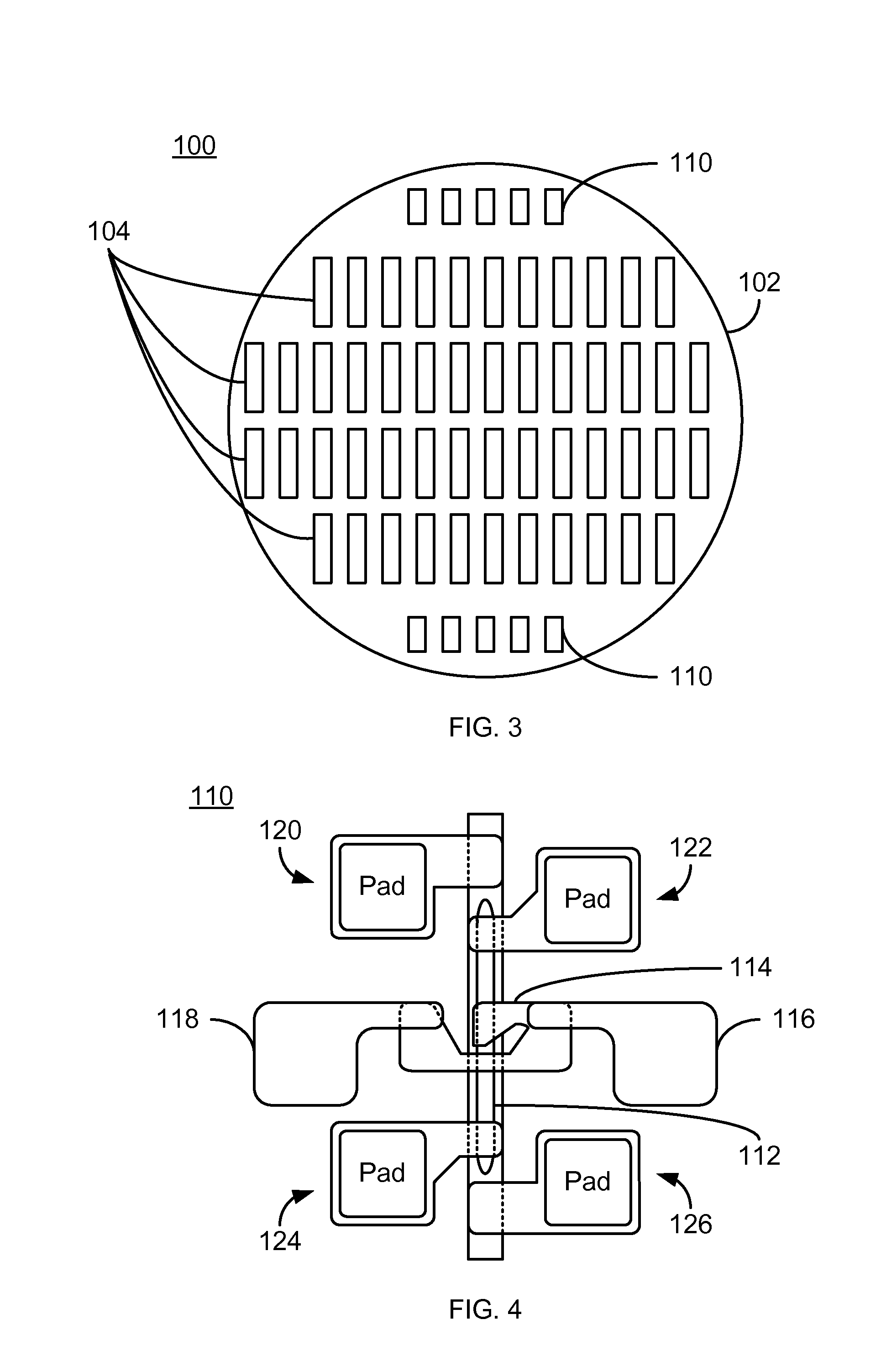
[0016]FIG. 3 is a diagram depicting an exemplary embodiment of an array 100 of heads formed on a substrate, or wafer 102. For clarity, FIG. 3 is not to scale. The array 100 includes heads 104 and test structures 110. For clarity, only some heads 104 and test devices 110 are labeled. Only four rows each having a particular number of heads 104 are shown for simplicity. However, in general, the wafer 102 has a larger number of rows and a larger number of heads 104 per row. For example, in some embodiments, the wafer 102 includes multiple flash fields, each of which includes 51 rows (or bars) of heads 104. Each of the heads 104 includes at least one read transducer. In other embodiments, each of the heads 104 may include at least one write transducer and at least one read transducer. The write transducers may be perpendicular magnetic recording (PMR), energy assisted magnetic recording (EAMR), or other writers. The read transducers typically include one or more tunneling magnetoresistiv...


PUM


Abstract

A method and system for testing a read transducer are described. The read transducer includes a read sensor fabricated on a wafer. A system includes a test structure that resides on the wafer. The test structure includes a test device and a heater. The test device corresponds to the read sensor. The heater is in proximity to the test device and is configured to heat the test device substantially without heating the read sensor. Thus, the test structure allows for on-wafer testing of the test device at a plurality of temperatures above an ambient temperature.

Description

BACKGROUND[0001]FIG. 1 depicts a plan view of a conventional array 10 of magnetic recording heads formed on a wafer, or substrate, 12. The conventional array 10 includes heads 14 that are formed in rows. Although only six rows of five, eleven, or fourteen heads are shown, typically a larger number of rows and a larger numbers of heads 14 per row are fabricated. The heads 14 include write transducer and read transducers. The write transducers may be perpendicular magnetic recording (PMR), energy assisted magnetic recording (EAMR), or other writers. The read transducers typically include tunneling magnetoresistive (TMR) or other analogous read sensors.[0002]FIG. 2 depicts a conventional method 50 for testing the heads 14. For simplicity, only a portion of the method 50 is described. The wafer 12 is heated to a desired temperature, via step 52. Step 52 may include placing the entire wafer 12 in a furnace. The furnace may then be set to the desired temperature, and time allowed for the ...

Claims


Application Information

Patent Timeline
IPC IPC(8): G01R31/28G11B5/455
CPCG01R31/2875G11B5/3166G11B5/455
Inventor SHANG, CHANGHEMAURI, DANIELEHO, KUOK SAN
Owner WESTERN DIGITAL TECH INC
Why Eureka
Try Eureka