Intrench profile

a technology of intrench and profile, applied in the field of intrench profile, can solve the problems of inability to use wet removal for sti recessing, difficult film removal, and inability to provide the selective removal necessary for such intricate details

Active Publication Date: 2013-10-03
APPLIED MATERIALS INC
View PDF3 Cites 221 Cited by
  • Summary
  • Abstract
  • Description
  • Claims
  • Application Information

AI Technical Summary

Benefits of technology

[0005]The present technology provides methods of removing dielectric materials of different qualities from within a trench that has been etched on a semiconductor substrate. The removal may be performed with dry etchant gases that are insensitive to the quality of a deposited oxide. By being insensitive, the dry etchant gases may remove different oxides at substantially similar rates. In this way, trenches that include multiple oxides of different qualities may be etched so that the profile within the trench is uniform across the different oxides.

Problems solved by technology

As semiconductor technology continues to evolve, these semiconductor substrate trenches continue to shrink in width, which makes film removal even more difficult.
Although a variety of etch techniques are available, few provide the selective removal necessary for such intricate detail.
However, such a wet removal cannot be used for STI recessing because the process chemistry and bath life often cannot be sufficiently controlled for such detailed etching.
Although this oxide selectivity is often acceptable during semiconductor processing, in STI recessing, the minute selectivity can cause concave profiles in the STI trenches where a liner oxide is present with a flowable oxide.
This slight concavity, or meniscus, can potentially cause integration issues with integrated passive device scaling and control gate polysilicon fill between the trenches.

Method used


Image

  • Intrench profile
  • Intrench profile
  • Intrench profile

Examples


examples

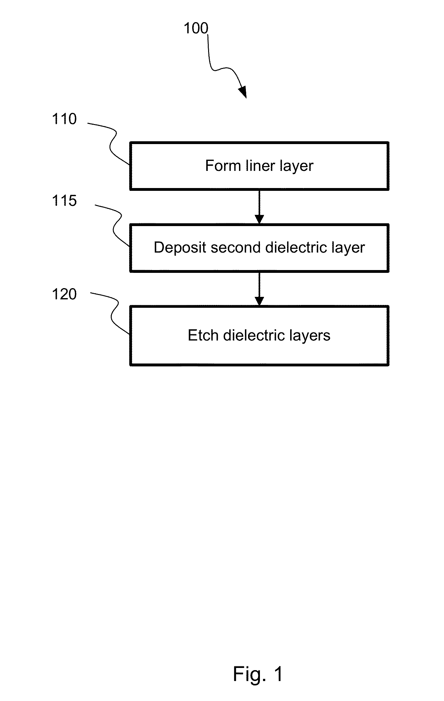
[0049]Comparative examples were made between etch selectivity using an etchant gas mixture with and without ammonia. The etches were conducted on a trench that was first lined with an HDP liner layer and then filled with a flowable oxide. The dielectrics were exposed to dry etchant gas mixtures containing nitrogen trifluoride and molecular hydrogen. In one example, the dry etchant gas also contained ammonia, while in a comparative example the dry etchant gas was substantially free of ammonia. As can be seen in Table I below, the dry etchant gas containing ammonia removes more of the flowable oxide in comparison to an HDP oxide than does the dry etchant gas that is substantially free of ammonia:

TABLE IETCH DEPTH OF DRY ETCHANT GASSelectivity ofHDP OxideFlowable OxideEtching of FlowableEtch DepthEtch DepthOxide with respect(angstrom)(angstrom)to HDP oxideDry Etchant Gas1141341.19ContainingAmmoniaDry Etchant Gas1141231.09SubstantiallyFree of Ammonia

[0050]FIGS. 4A and 4B show comparativ...


PUM

PropertyMeasurementUnit
temperatureaaaaaaaaaa

Abstract

A method of etching a recess in a semiconductor substrate is described. The method may include forming a dielectric liner layer in a trench of the substrate where the liner layer has a first density. The method may also include depositing a second dielectric layer at least partially in the trench on the liner layer. The second dielectric layer may initially be flowable following the deposition, and have a second density that is less than the first density of the liner. The method may further include exposing the substrate to a dry etchant, where the etchant removes a portion of the first liner layer and the second dielectric layer to form a recess, where the dry etchant includes a fluorine-containing compound and molecular hydrogen, and where the etch rate ratio for removing the first dielectric liner layer to removing the second dielectric layer is about 1:1.2 to about 1:1.

Description

CROSS-REFERENCES TO RELATED APPLICATIONS[0001]This application claims the benefit of U.S. Provisional Application No. 61 / 539,279, filed Sep. 26, 2011, entitled “Improved Intrench Profile.” The entire disclosure of which is incorporated herein.BACKGROUND[0002]Semiconductor processing often include many distinct manufacturing steps. With the current state of technology, circuit components are routinely formed on nanometer scales, and sensitive manufacturing techniques are required. For instance, with integration schemes for shallow-trench-isolation (“STI”) gate formation, a sacrificial film must be removed preferentially in the presence of a selective material in a nanometer thin trench. As semiconductor technology continues to evolve, these semiconductor substrate trenches continue to shrink in width, which makes film removal even more difficult.[0003]These small width trenches create a need for delicate etching techniques. Although a variety of etch techniques are available, few pro...

Claims


Application Information

Patent Timeline
Patent Type & Authority Applications(United States)
IPC IPC(8): H01L21/762
CPCH01L21/76224H01L21/3081H01L21/3065
Inventor SAPRE, KEDARINGLE, NITINTANG, JING
Owner APPLIED MATERIALS INC
Why Eureka
Try Eureka