Method of making replacement collecting electrodes for an electrostatic precipitator

a technology of electrostatic precipitator and collecting electrode, which is applied in the direction of electrode cleaning, chemistry apparatus and processes, colloidal chemistry, etc., can solve the problems of small diameter wire design, heavy fines and production cuts, and low production efficiency, and achieves easy shipping and maximum electrical conductivity.

Inactive Publication Date: 2008-10-21
HAMON RES COTTRELL
View PDF24 Cites 11 Cited by
  • Summary
  • Abstract
  • Description
  • Claims
  • Application Information

AI Technical Summary

Benefits of technology

[0011]The method of making a replacement collecting electrode for an electrostatic precipitator of this invention includes forming a plurality of vertical collecting electrode sections, wherein each section includes spaced planar collecting electrode portions separated by spaced vertical tubular portions, wherein the tubular portions may be coaxially aligned for assembly. As used herein, the term “vertical” refers to the final orientation of the planar collecting portions and tubular portions. The collecting sections are then aligned with the vertical tubular portions coaxially aligned. The method of this invention then includes inserting interconnecting support rods into the opposed tubular portions of the adjacent collecting sections and forming a plurality of aligned interconnected collecting sections. As used herein, the term interconnecting support “rod” includes a solid or tubular rod, but in a preferred method of compressing the interconnected collector sections disclosed herein, the interconnecting rods are tubular. Finally, one preferred embodiment of the method of this invention includes compressing the interconnected collecting sections to form a rigid assembly of interconnected collecting sections able to withstand and transmit rapping forces. In one preferred embodiment of the method of this invention, the collecting sections are assembled within the electrostatic precipitators, as described further below. The vertical tubular portions may be diamond-shaped, as described above, providing superior performance. However the tubular portions of the collecting electrode sections may be any tubular shape which permits interconnecting the collecting electrode sections as described.
[0013]The rigidity of the collecting electrode of this invention may be further improved by first inserting anvil pipes into the opposed ends of adjacent tubular portions of the vertical collecting sections and permanently affixing the anvil pipes in the tubular portions of the collecting electrode sections, such as by welding the anvil pipes in the tubular portions at the place of manufacture of the collecting electrode sections This embodiment of the method of this invention then includes inserting the interconnecting support rods having an outside diameter generally equal to or slightly smaller than an internal diameter of the anvil pipes, wherein the anvil pipes add strength and rigidity to the assembled collecting electrode. In one preferred embodiment, anvil pipes are inserted in each end of the tubular portions of the adjacent collecting electrode sections, each having a length less than one-half the axial length of the tubular sections and permanently securing the anvil pipes in place, as by welding. In one preferred embodiment, the anvil pipes include a stop adjacent the inner end of the anvil pipes to prevent the interconnecting support rods from passing through the tubular portions of the collecting electrode sections and providing the correct projecting length or height of the interconnecting support rods. A stop may be provided for example at the inner end of the anvil pipes simply by crimping the end of the anvil tubes received in the tubular portion prior to insertion in the tubular portions of the collecting section.
[0015]The method of making a replacement collecting electrode for an electrostatic precipitator of this invention thus eliminates the need for high lift devices, such as a crane, to raise a single piece large collecting electrodes into the precipitator, eliminates the need to relocate external equipment or make penetrations or holes into existing structures that may block access into the electrostatic precipitator internals, provides a uniform profile of its emission surface so as not to create areas of excess sparking on its surface, maintains correct rigid alignment of the collecting electrode surface, maximizes electrical conductivity across the collecting electrode and provides complete compatibility with existing collecting electrodes. Further, special tools or welding is not required at the site of the electrostatic precipitator because the collecting electrode sections may be manufactured at a manufacturing facility and easily shipped in small sections to the electrostatic precipitator for final assembly.

Problems solved by technology

When a particulate laden or polluted waste gas is passed at low velocity through this electron field, the particulates in the gas stream will become negatively charged.
More recently, environmental regulations have become so strict that even the slightest emission violation or a fundamental loss of a part of a precipitator, can result in heavy fines and production cut-backs and shut down.
While the original small diameter wire design was very efficient electrically and cost efficient, the small diameter wire design was prone to breakage and failure, particularly due to age, sparking and stress from the precipitator internal cleaning rapping or vibration system which causes the agglomerated particulates to fall from the collecting electrodes.
However, while the issues of normal operational collecting and discharge electrode failure has been resolved, there will still be failures that relate to general aging, or failure due to temperature surges caused by process upset conditions or precipitator fires which can damage or destroy the internal components of the electrostatic precipitator.
As will be understood by those skilled in this art, it is very difficult and expensive to replace the collecting electrodes of an electrostatic precipitator.
Replacement of the collecting electrodes results in lengthy down time for the precipitator, always requiring that the entire electrostatic precipitator and process be shut down.
There are also many instances where the owner of the electrostatic precipitator desires to upgrade an older existing precipitator that has good external casing, but may suffer from frequent failure of the internal electrical components or require efficiency or reliability upgrades.

Method used


Image

  • Method of making replacement collecting electrodes for an electrostatic precipitator
  • Method of making replacement collecting electrodes for an electrostatic precipitator
  • Method of making replacement collecting electrodes for an electrostatic precipitator

Examples


Embodiment Construction

[0029]The attached drawings illustrate one embodiment of a method of making replacement collecting electrodes for an electrostatic precipitator of this invention. However, as will be understood by those skilled in this art, the disclosed method is provided for illustrative purposes only and various modifications may be made to the disclosed method of this invention within the purview of the appended claims.

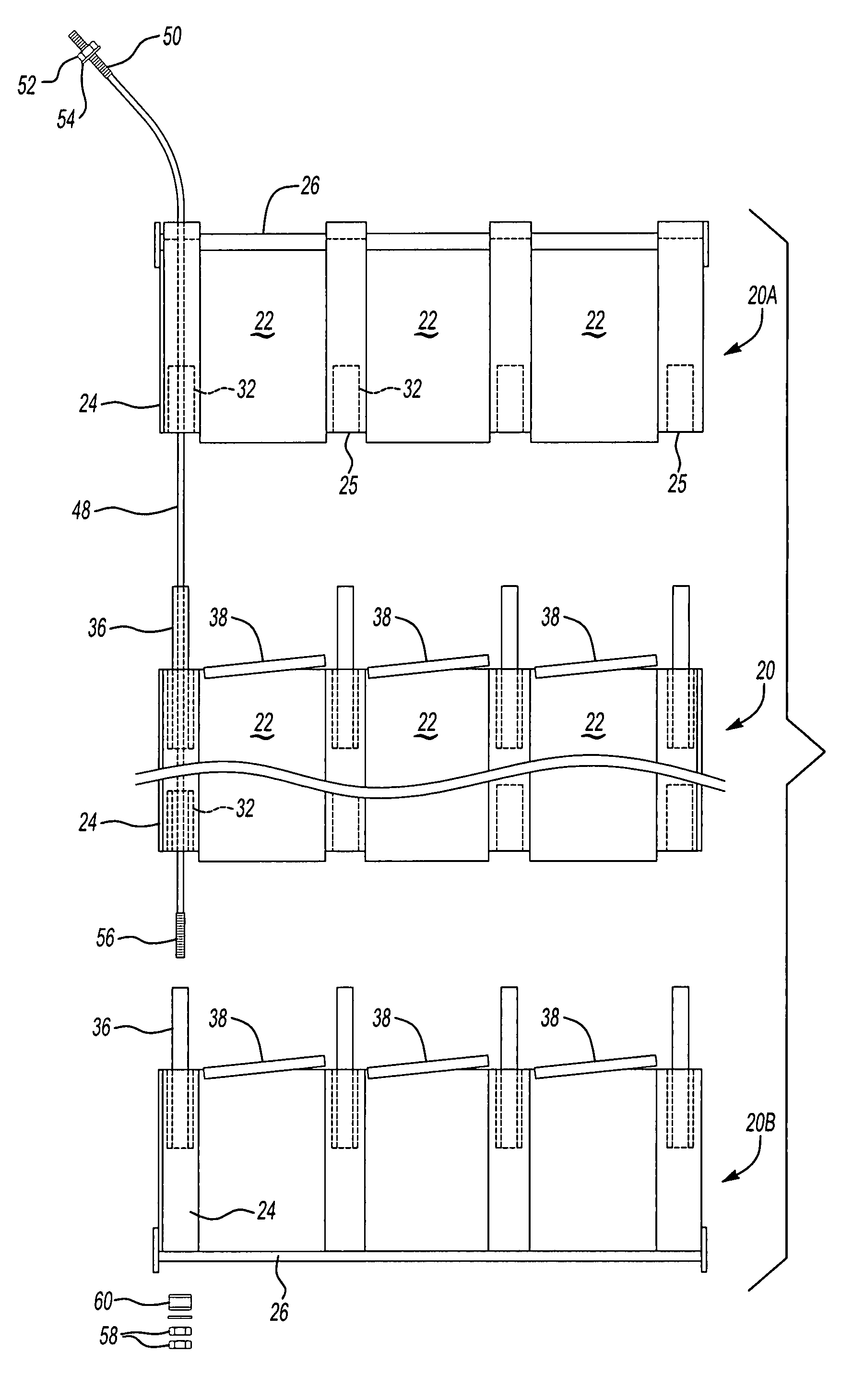
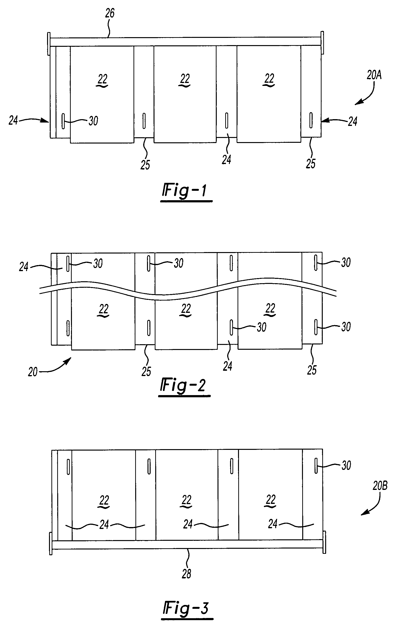
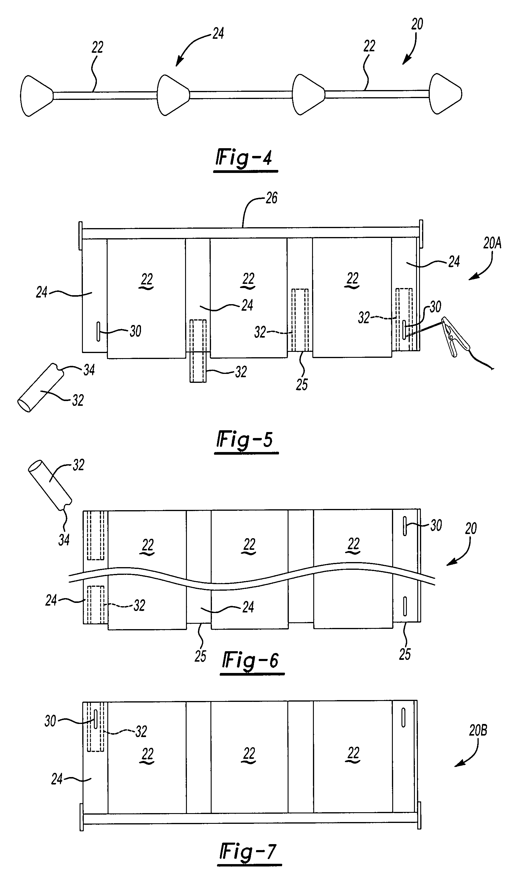
[0030]A first step of the method of this invention is to form a plurality of collecting electrode sections 20. In one preferred embodiment, the collecting electrode sections are identical or substantially similar to reduce cost and simplify construction as described below. FIGS. 1 to 3 illustrate one embodiment of the collecting electrode sections 20, wherein 20A in FIG. 1 is an upper collecting electrode section and 20B in FIG. 3 is a lower section. For ease of description, the collecting electrode sections will be referred to generically by reference number 20. Each of the colle...


PUM


Abstract

A method of forming a modular collecting electrode for an electrostatic precipitator, including forming a plurality of horizontal collecting electrode sections, each section having vertical planar portions separated by vertical tubular portions, and wherein the method includes inserting interconnecting support elements into the tubular portions of adjacent collector electrode sections and compressing the interconnected electrode sections to form a rigid modular assembly. In one preferred embodiment, the method includes applying stiffening members across the ends of the planar portions of adjacent electrode sections for transmitting rapping forces through the assembled sections.

Description

RELATED APPLICATION[0001]This application claims priority to U.S. Provisional Patent Application Ser. No. 60 / 775,889 filed Feb. 23, 2006.FIELD OF THE INVENTION[0002]This invention relates a method of making modular rigid collecting electrodes for replacement in situ of damaged collecting electrodes or reconfiguration of or general rebuild of an electrostatic precipitator without requiring removal of the casing or superstructure of the electrostatic precipitator, thereby significantly reducing costs and down time during repair.BACKGROUND OF THE INVENTION[0003]Electrostatic precipitators are an efficient and economic way of collecting particulates suspended in a waste gas stream. The electrostatic precipitator technology was first invented and implemented in the early 1900s by Research-Cottrell, the predecessor in interest of the assignee of this application.[0004]In the electrical precipitation process of an electrostatic precipitator, a chamber filled with large parallel spaced cond...

Claims


Application Information

Patent Timeline
Patent Type & Authority Patents(United States)
IPC IPC(8): B03C3/86
CPCB03C3/86Y10S55/38
Inventor STRAUSS, ROBERT A.
Owner HAMON RES COTTRELL
Why Eureka
Try Eureka