

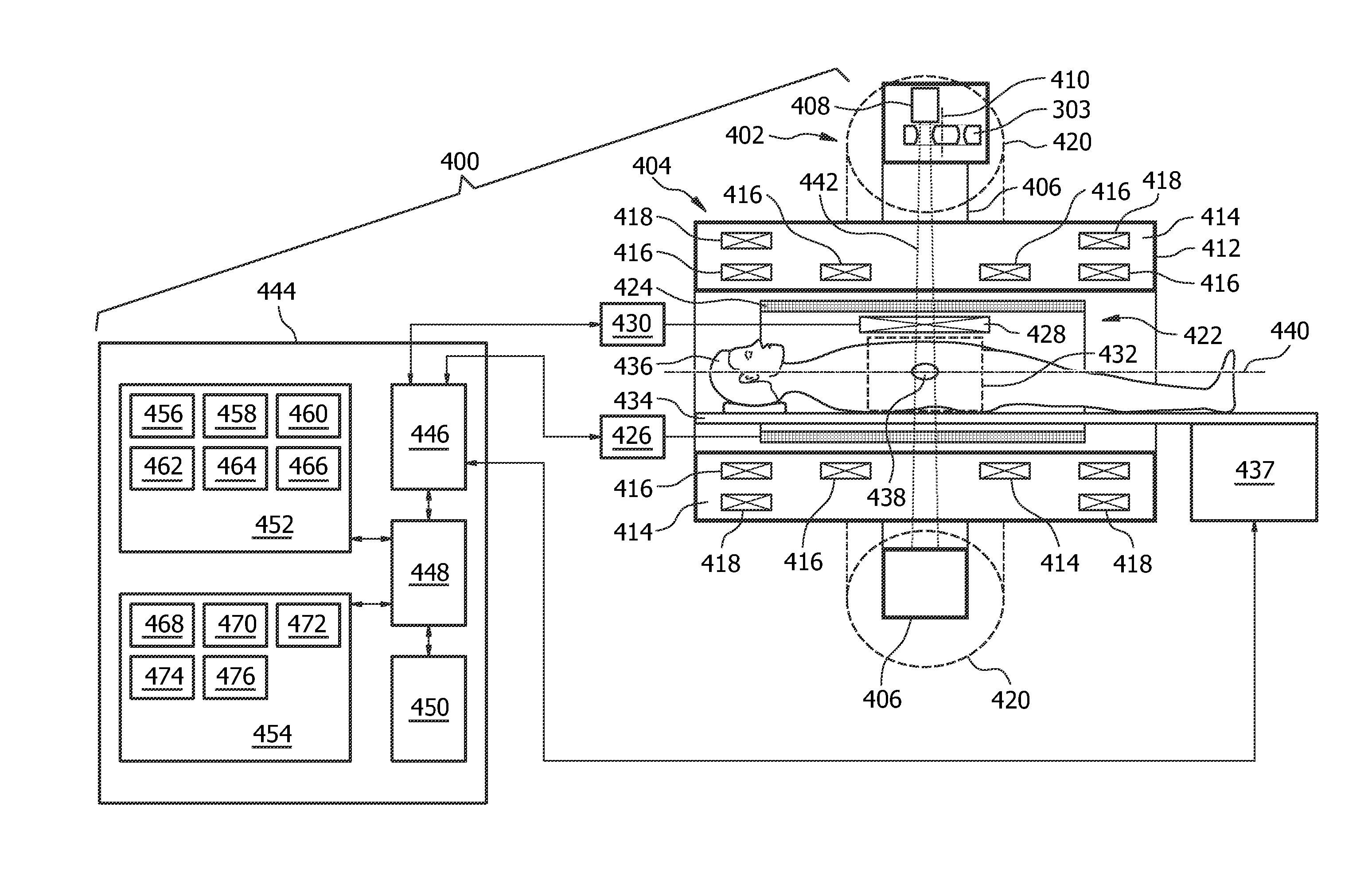
Therapeutic apparatus comprising a radiotherapy apparatus, a mechanical positioning system, and a magnetic resonance imaging system
a technology of magnetic resonance imaging and radiotherapy apparatus, which is applied in radiation therapy, medical science, therapy, etc., can solve the problems of high cost of multi-leaf collimators, and achieve the effect of accurate radiation direct into the target zon
- Summary
- Abstract
- Description
- Claims
- Application Information
AI Technical Summary
Benefits of technology
Problems solved by technology
Method used
Image

Examples
Embodiment Construction
[0084]Like numbered elements in these figures are either equivalent elements or perform the same function. Elements which have been discussed previously will not necessarily be discussed in later figures if the function is equivalent.
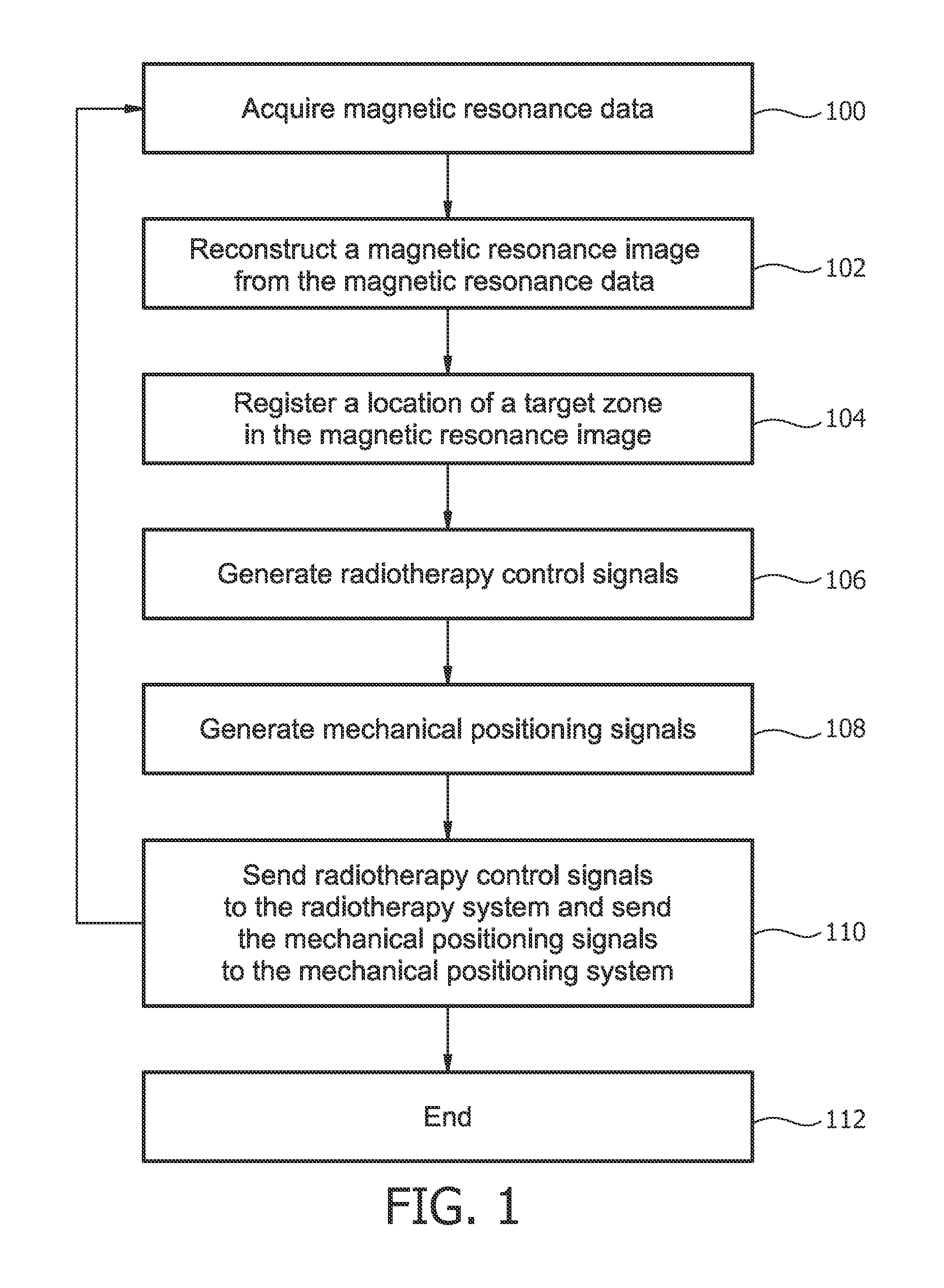
[0085]FIG. 1 shows a flow diagram which illustrates an embodiment of a method according to the invention. The method may also be implemented or performed as a computer-implemented method or as a computer program product in the form of machine executable instructions.
[0086]In step 100 magnetic resonance data is acquired. In step 102 a magnetic resonance image is reconstructed from the magnetic resonance data. Typically magnetic resonance data is acquired for a volume or a thin volume referred to as a slice. References to a magnetic resonance image may also refer to multiple images or multiple slices. Next in step 104 a location of the target zone is registered in the magnetic resonance image. This may be performed using standard image registration techni...
PUM
 Abstract
Description
Claims
Application Information