

Electrode for electric discharge machining
a technology of electro-discharge machining and electrode, which is applied in the direction of electrical-based machining electrodes, metal-working apparatus, manufacturing tools, etc., can solve the problems of electrode being badly worn, electrode not desirable for an application to which precision is required, and easy to increase the machining speed, etc., to achieve the effect of improving the machining speed, improving the wear ratio of the electro-discharge machining electrode, and superior electric discharge characteristics
- Summary
- Abstract
- Description
- Claims
- Application Information
AI Technical Summary
Benefits of technology
Problems solved by technology
Method used
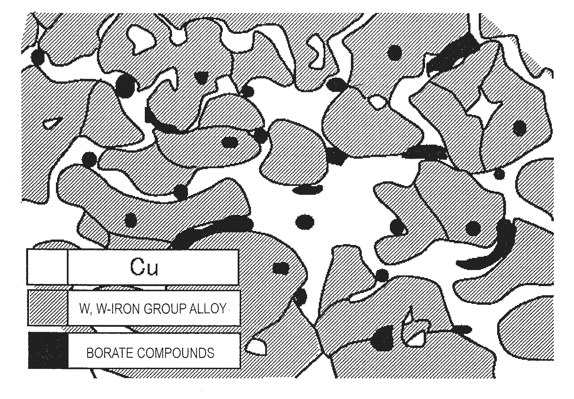
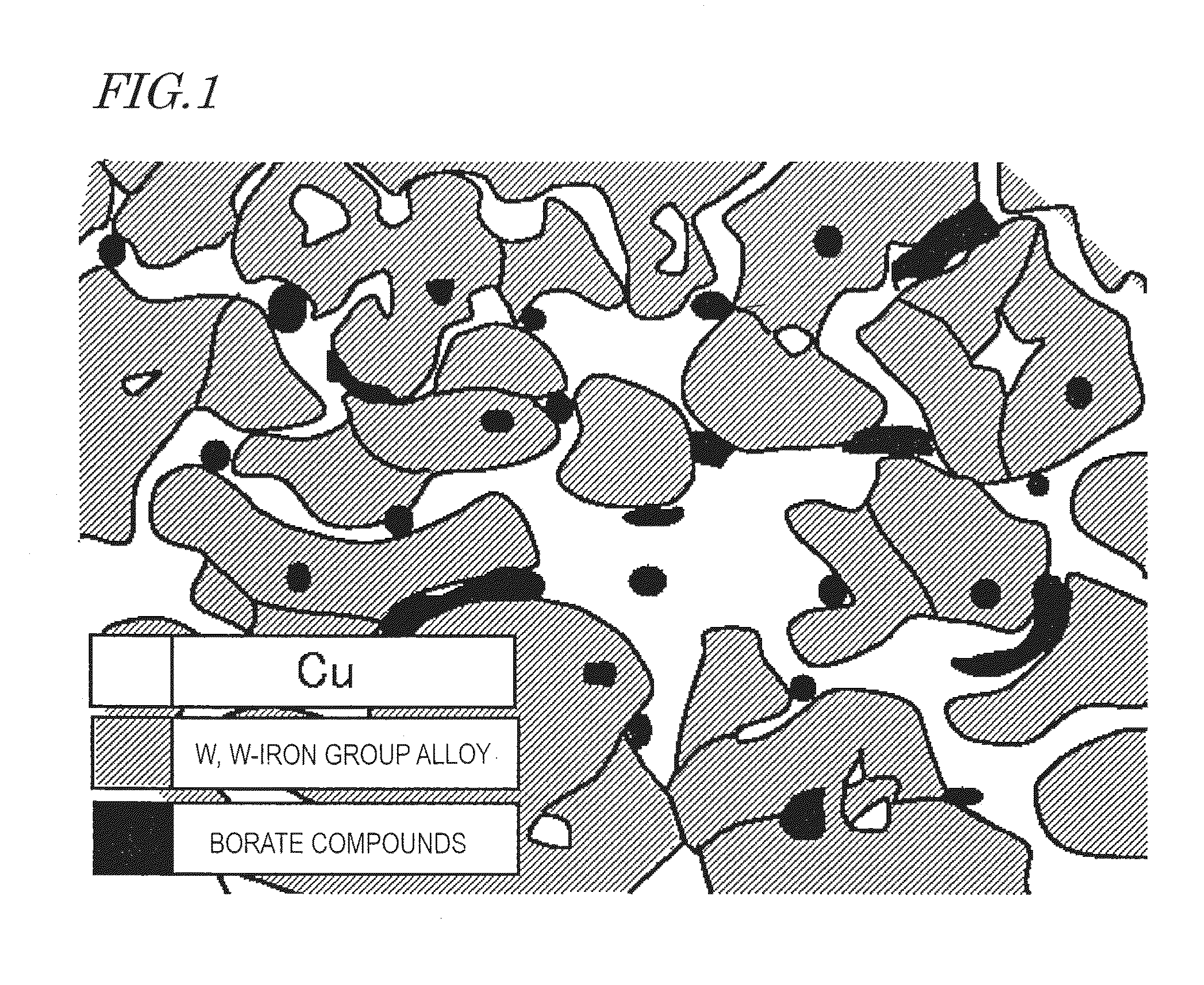
Image


Examples
example 1
[0095]As a material to form W skeleton, W of 79 parts by mass having an average particle diameter of 4 μm, Ni of 1 parts by mass having an average particle diameter of 1 μm, and Sr borates of 0.4 external parts by mass having an average particle diameter of 7 μm was prepared.
[0096]The Sr borates to be used were obtained by mixing SrCO3 and B2O3 having an average particle diameter of 5 μm at the mass ratio of 2:1, and then baking for thirty minutes at 1050° C. under the atmospheric environment.
[0097]The powder thereof was mixed by Henschel mixer for thirty minutes, thereby obtaining the mixed powder.
[0098]Then, the mixed powder was pressed by using a die at a pressure of 50 MPa, thereby obtaining a rod-like compact.
[0099]A recessed portion in which the compact was sufficiently accommodated was provided in a heat-resistant container, and the compact was placed in the recessed portion. Then, the sintering was performed for sixty minutes at 1150° C. in the H2 atmosphere, thereby obtaini...
example 2
[0119]Next, the same experiments as those of Specimen 1 were performed by using a specimen in which the mass ratio between M1 and M2 metal was varied, or a specimen in which different kinds were selected in the iron group metal, the alloy of M2 and iron group metal, and the borate compounds of one or more of Mg, Ca, Sr, Ba, and the rare earth metals.
[0120]The compositions of the respective specimens are shown in Table 6 and Table 7, and the evaluated results are shown in Table 8 and Table 9.
[0121]As for W, the iron group metal, and the alloy of iron group metal, X-ray diffraction was performed for the material after the sintering, and the amounts were identified by means of the peak ratio.
TABLE 6Alloy ofM2 andBorateM1 (A)M2 (B)IronIron groupcompounds (C)(Cu, Ag)(W, Mo)group (B)metal (B)(externalSpecimen(pars(pars(parts(partsparts byNo.by mass)by mass)by mass)by mass)mass)*101 3Cu96.5W00.5 W—Ni0.4SrB2O41025Cu94.5W00.5 W—Ni0.4SrB2O410310Cu89.5 W00.5 W—Ni0.4SrB2O410420Cu79.5W00.5 W—Ni0...
example 3
[0130]The production of a specimen was performed under the same conditions as those in Specimen 1, other than the points that as the starting materials, (A): Cu of 20 parts by mass, (B): W of 79.5 parts by mass and Ni of 0.5 parts by mass, and (C): SrB2O4 of 0.5 external parts by mass was used, and the atmosphere of infiltration was changed from the H2 atmosphere to the mixed atmosphere of H2 and Ar. For this specimen, the same test and evaluation as those for Specimen 1 were performed. As a result, it was confirmed that the specimen could be suitably used as the electric-discharge machining electrode as shown below.
[0131]Machining speed of 90.0 mm / sec, Wear ratio of 8.9%, and the surface roughness of 15.0 Ry(μm).
[0132]The specimen is referred to as Specimen 200. When Specimen 200 was observed by EPMA mapping and X-ray diffraction, there was a portion in which Sr, Ni, W, and O were observed in the same portion together with Cu, W, W-—i alloy, and Sr2B2O5. Thus, the investigation was...
PUM
| Property | Measurement | Unit |
|---|---|---|
| Percent by mass | aaaaa | aaaaa |
| Percent by mass | aaaaa | aaaaa |
| Percent by volume | aaaaa | aaaaa |
Abstract
Description
Claims
Application Information