Further, directing such signal connections laterally to the transducer array to the front side thereof, may undesirably and adversely affect the
diameter of the
catheter (i.e., a larger
diameter catheter may undesirably be required in order to accommodate the signal connections passing about the transducer array).
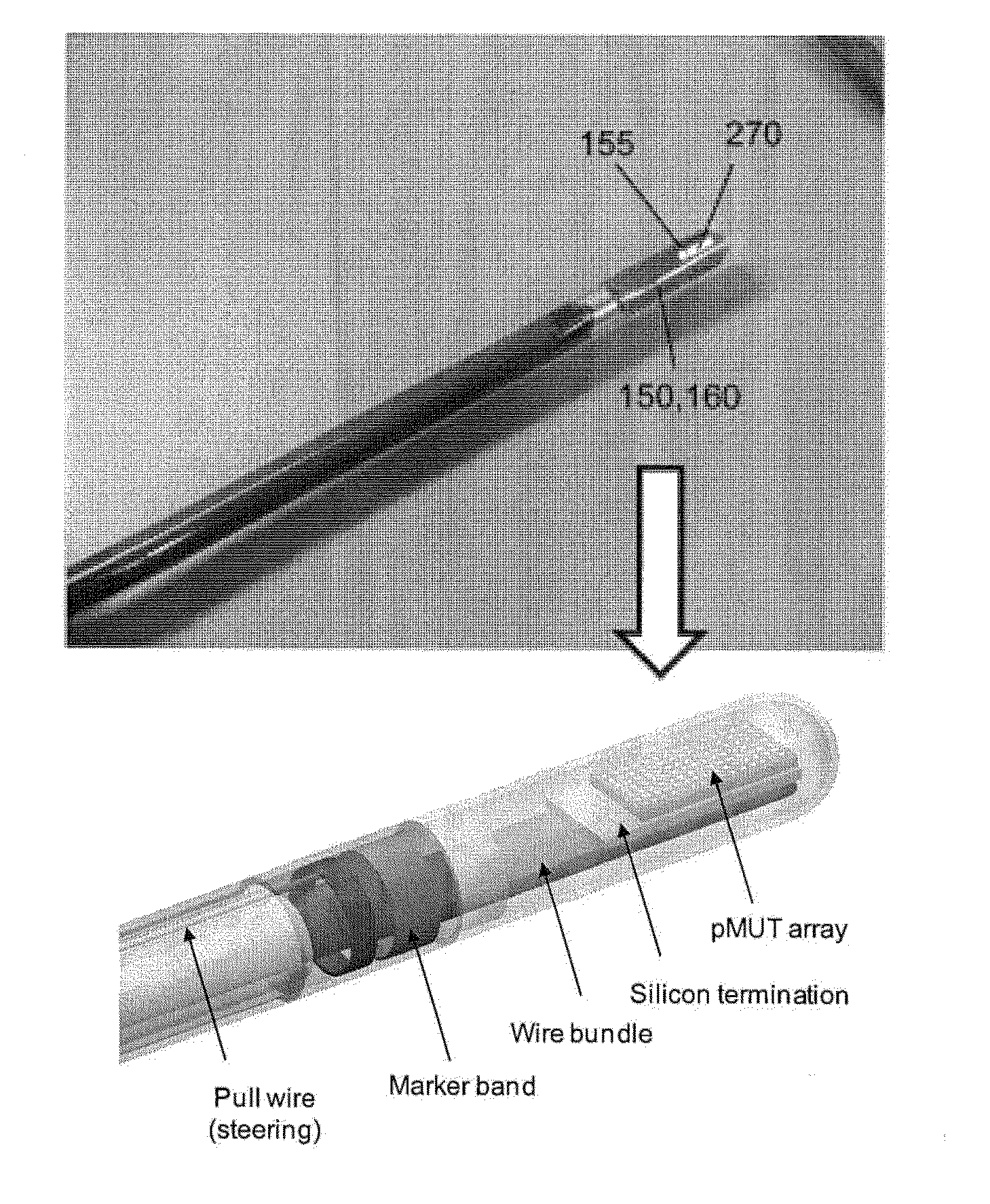
However, for a forward-looking transducer array in a relatively small catheter /
endoscope, such an arrangement may be difficult to implement due to the severe bend requirement for the flex cable (i.e., about 90 degrees), which may also be compounded by the number of conductors comprising the flex cable and the engagement of the electrically-conductive signal leads to the pMUT devices (also about a bend of about 90 degrees), in order for the transducer array to be disposed within the lumen of the catheter /
endoscope.
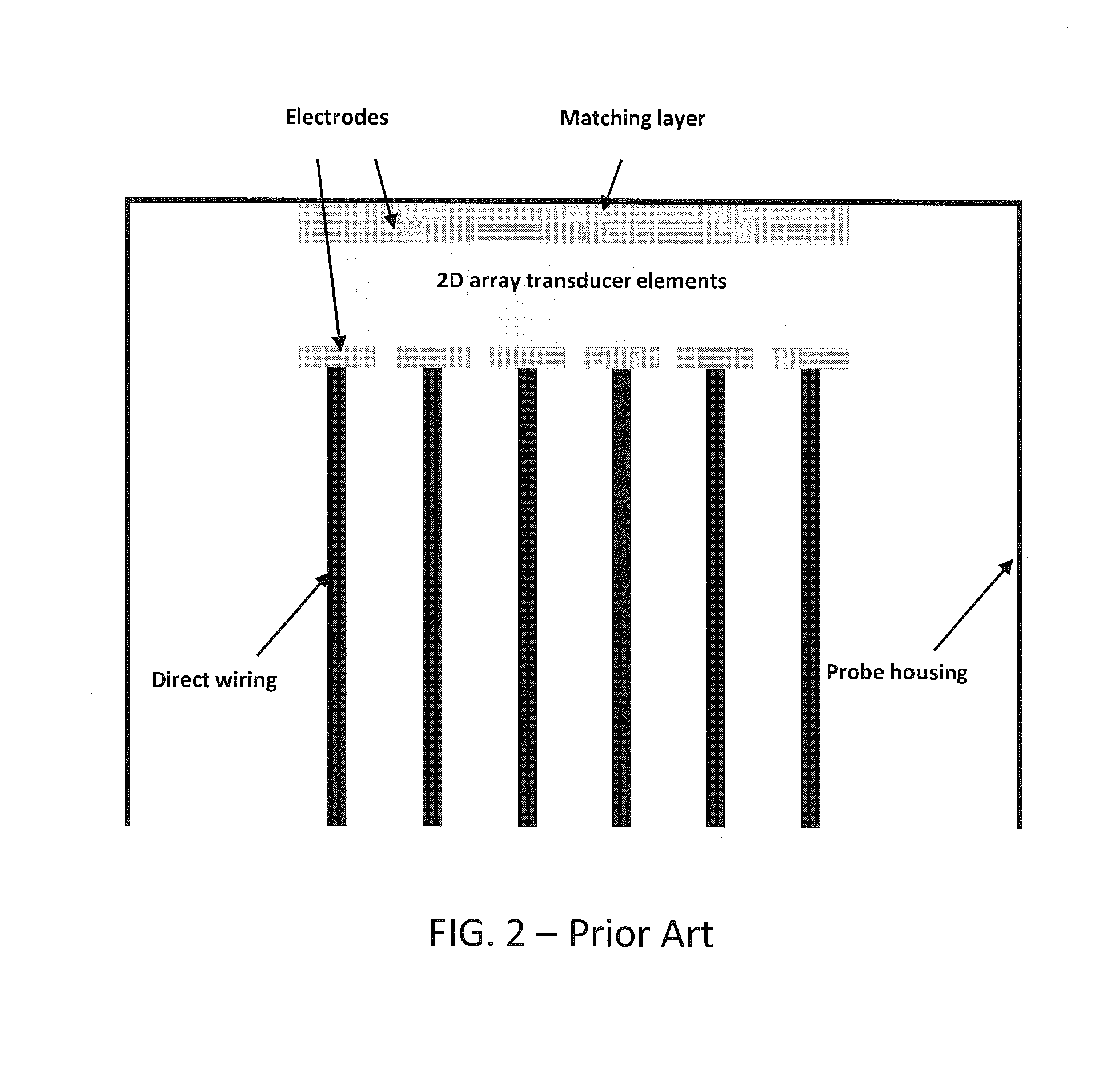
Further, for a forward-looking two-dimensional (2D) transducer array, signal
interconnection with the individual pMUT devices may also be difficult.
However, as the number of wires and / or flex cable assemblies increases, the more difficult it becomes to bend the larger amount of signal interconnections about the ends of the transducer device to achieve the 90 degree bend required to integrate the transducer array into a catheter /
endoscope.
In addition, the
pitch or distance between adjacent pMUT devices may be limited due to the required number of wires / conductors.
Accordingly, such limitations may undesirably limit the minimum size (i.e.,
diameter) of the catheter / endoscope that can readily be achieved.
However, the space between the back side of the transducer array and the catheter wall may be limited, particularly, for example, in catheters having an inner diameter of about 3 mm or less.
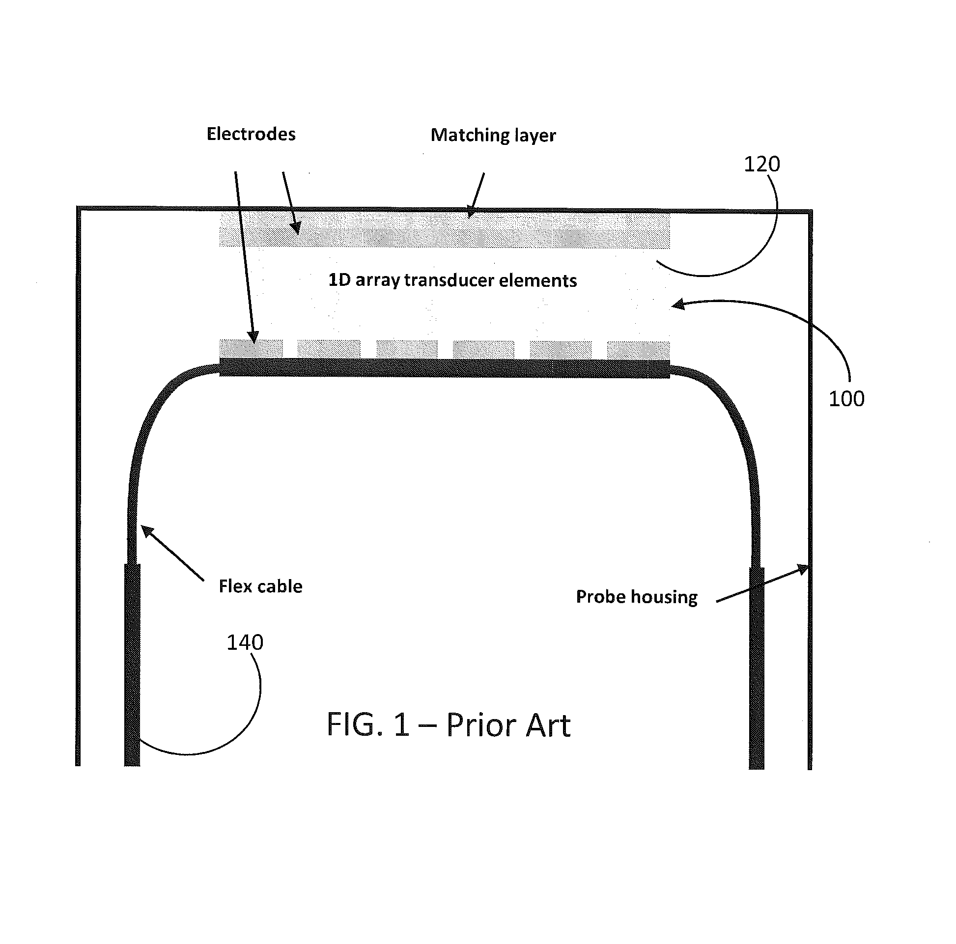
Further, the previously-noted thicker stacks placed in a transducer arrangement, as illustrated in FIG. 2 and including a transducer array,
signal processing IC's and connective elements, may not necessarily be feasible in instances of the limited catheter inner diameter.
Such a configuration may also undesirably impart mechanical stresses to the signal lead (which must be bent about 90 degrees to be routed from the transducer and along the catheter) and / or transducer array interface due to the thickness of the transducer / IC stack and the limited space available across the catheter diameter.
However, such a configuration may be limited with respect to the number of transducer elements that can be practically implemented due, for instance to the resolution limit of the signal traces of the flex cable.
Further, for 2D transducer arrays, high element counts (e.g., 196 to 1,600 elements) may require multilayer flex cabling for attachment and
interconnection of all transducer elements, further increasing cost and complexity of the flex cabling.
Further, for 2D arrays, a flex cable containing several hundred conductors may be too large in dimension (i.e., too wide and / or too thick) to fit within a 3 mm diameter catheter.
A multiple level flex cable may thus be undesirably expensive, difficult (or impossible) to manufacture, and may not be robust due to a relatively
high probability of short circuits in light of the increased number of
metal levels and vias.
Other disadvantages of multilayer flex cabling may include higher conductor impedance, higher
insertion loss, greater cross
coupling between element traces, and higher shunt-to-ground
capacitance which may reduce
penetration depth compared to coaxial cabling (though typical coaxial cabling cannot be made with sufficiently
fine pitch to be used in such catheter applications).
Thus for a catheter that is 3 feet in total length, multiple flex cable segments must be serially connected in order to complete the
electrical connection through the entire catheter, thereby undesirably increasing complexity and cost of assembly.

