Electro-optic apparatus and electronic apparatus

a technology of optical apparatus and electronic apparatus, applied in non-linear optics, instruments, optics, etc., can solve the problems of small thermal damage to organic el, non-conformity, liquid crystal deterioration, etc., and achieve excellent moisture resistance, suppress the effect of change (the deterioration) in display performance due to external moistur

Inactive Publication Date: 2013-10-17
SEIKO EPSON CORP
View PDF5 Cites 31 Cited by
  • Summary
  • Abstract
  • Description
  • Claims
  • Application Information

AI Technical Summary

Benefits of technology

[0014]The electro-optic material, which is enclosed by the first substrate, the second substrate, and the organic sealant, is further enclosed by the second substrate, the third substrate, and the inorganic sealant, resulting in being enclosed twofold. Because the second substrate, the third substrate, and the inorganic sealant have excellent moisture resistance, the penetration of external moisture (water) into the area enclosed twofold is suppressed. That is, the electro-optical apparatus with excellent moisture resistance is provided in which the penetration of water into the electro-optic material is suppressed, and thus the change (the deterioration) in the display performance due to the external moisture is suppressed.
[0015]Additionally, because the organic sealant is interposed between the inorganic sealant and the electro-optic material, and the inorganic sealant and the electro-optic material are separated from each other, the inorganic sealant prevents the electro-optic material from being contaminated. Additionally, the deterioration in the electro-optic material (the thermal decomposition) is suppressed during the process of forming the inorganic sealant (the local heating by the laser beam). Therefore, the bad influence on the electro-optic material (the thermal decomposition, the contamination, and the like) is suppressed by forming the inorganic sealant, and thus the electro-optic apparatus is provided that is excellent in display quality.

Problems solved by technology

As a result, nonconformity, such as irregularity, occurs on display.
Because the low-melting-point glass is melted and solidified by local heating through the use of a laser beam, thermal damage to the organic EL is small.
However, when the method disclosed in JP-A-10-74583 is applied to the liquid crystal display apparatus, there is a problem in that the liquid crystal deteriorates (thermal decomposition) in a process of melting and solidifying the low-melting-point glass (the local heating though the use of the laser beam).
However, this causes a problem in that the liquid crystal is contaminated by the low-melting-point glass and display irregularity occurs.
Additionally, because the protective film makes it difficult for the heat of the inorganic sealant locally heated by the laser beam to be transferred to the metal film, nonconformity is suppressed that is called a crack in the insulating film covering a hillock of the metal film and the metal film.
That is, the heat of the inorganic sealant is difficult to conduct below the dielectric film.
The formation of the dielectric film, configured from any one of silicon oxide, silicon nitride, silicon oxynitride and aluminum oxide, between the metal film and the inorganic sealant makes it difficult for the heat of the inorganic sealant locally heated by the laser beam to be conducted to the metal film.

Method used


Image

  • Electro-optic apparatus and electronic apparatus
  • Electro-optic apparatus and electronic apparatus
  • Electro-optic apparatus and electronic apparatus

Examples


first embodiment

[0057]Outline of Display Apparatus

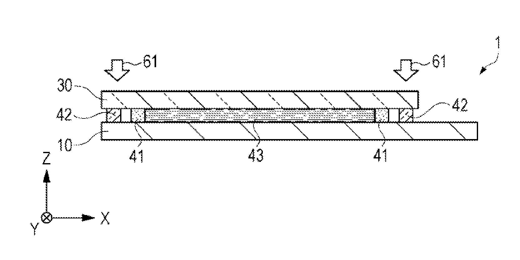
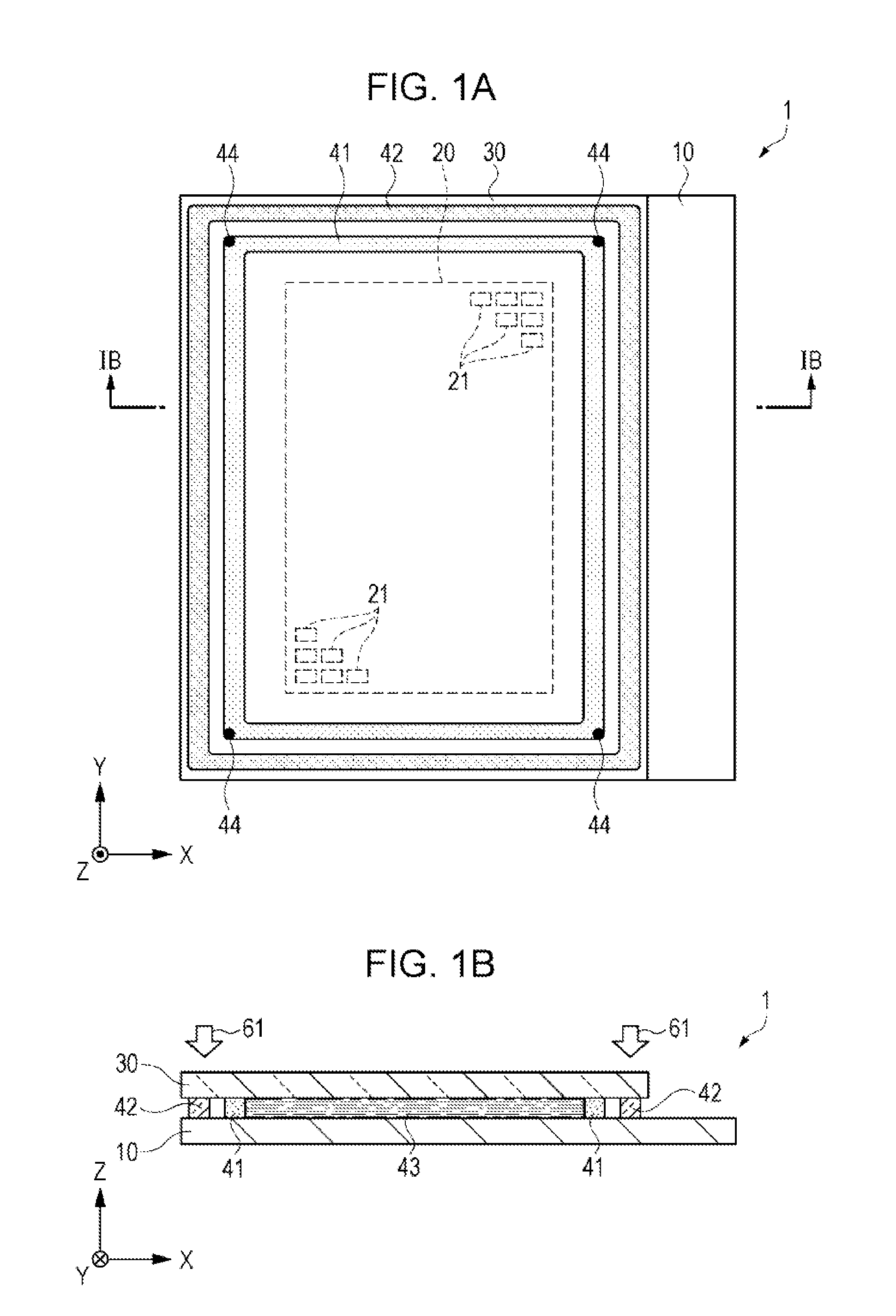
[0058]FIGS. 1A and 1B are diagrams, each illustrating a configuration of a display apparatus according to a first embodiment. FIG. 1A is a schematic plan view. FIG. 1B is a schematic cross-sectional view of FIG. 1A that is taken along a line IB-IB. First, an outline of the display apparatus as an electro-optic apparatus according to the first embodiment is described referring to FIGS. 1A and 1B. In addition, an arrow in FIG. 1B indicates an incident direction of a laser beam.

[0059]A display apparatus 1 is a liquid crystal display apparatus which is sealed twofold by an organic sealant 41 and an inorganic sealant 42, and in which penetration of moisture into the inside is suppressed. The display apparatus 1 is configured to include an opposite substrate 30, an element substrate 10, the organic sealant 41 that is interposed between and supported by the element substrate 10 and opposite substrate 30, the inorganic sealant 42, liquid crystal 43, a condu...

second embodiment

[0110]Outline of Display Apparatus

[0111]FIGS. 5A and 5B are diagrams, each illustrating a configuration of a display apparatus according to a second embodiment. FIG. 5A is a schematic plan view. FIG. 5B is a schematic cross-sectional view of FIG. 5A that is taken along a line VB-VB. An outline of the display apparatus as an electro-optic apparatus according to the second embodiment is described below, referring to FIGS. 5A and 5B.

[0112]Furthermore, in each drawing including FIGS. 5A and 5B, the same constituent parts as those in the first embodiment are given like reference numerals. Additionally, the same descriptions are omitted, and descriptions are provided, with a focus being placed on the differences.

[0113]A main difference from the first embodiment is that a new protective substrate 51 is formed on a display apparatus 2 according to the second embodiment. Additionally, there are also differences from the first embodiment in that the display apparatus 2 is a reflection type li...

third embodiment

Outline of Display Apparatus

[0138]FIGS. 9A and 9B are diagrams, each illustrating a configuration of a display apparatus according to a third embodiment. FIG. 9A is a schematic plan view. FIG. 9B is a schematic cross-sectional view of FIG. 9A that is taken along a line IXB-IXB. An outline of the display apparatus as the electro-optic apparatus according to the third embodiment is described below, referring to FIGS. 9A and 9B.

[0139]Furthermore, in each drawing including FIGS. 9A and 9B, the same constituent parts as those in the first embodiment are given like reference numerals. Additionally, the same descriptions are omitted, and descriptions are provided, with a focus being placed on the differences.

[0140]A main difference from the first embodiment is that two protective substrates 52 and 53 are formed on a display apparatus 3 according to the third embodiment. Additionally, a shape of a protective film 15 (refer to FIG. 10A) also is different from that of the protective film acco...


PUM

PropertyMeasurementUnit
shapeaaaaaaaaaa
melting-pointaaaaaaaaaa
melting pointaaaaaaaaaa

Abstract

Provided is an electro-optic apparatus including an organic sealant that seals a first substrate and a second substrate, an inorganic sealant that surrounds the organic sealant which seals the first substrate and the second substrate, and an electro-optic material that is enclosed within an area surrounded by the organic sealant.

Description

BACKGROUND[0001]1. Technical Field[0002]The present invention relates to an electro-optic apparatus and an electronic apparatus equipped with the electro-optic apparatus.[0003]2. Related Art[0004]A liquid crystal display apparatus, one example of an electro-optic apparatus is widely used as an optical modulation unit (a light valve) of a projection type display apparatus such as a projector. The liquid crystal display apparatus is configured to include a pair of glass substrates on which an alignment film is formed, an organic sealant such as epoxy resin that glues the pair of glass substrates together, liquid crystal as an electro-optic material, which is enclosed inside an area sectioned with the organic sealant, an alignment film that controls an alignment state of the liquid crystal, and others.[0005]Because strong light is emitted in the liquid crystal display apparatus in use for the light valve, an inorganic alignment film is used, such as SiO2 that is excellent in light resi...

Claims


Application Information

Patent Timeline
Patent Type & Authority Applications(United States)
IPC IPC(8): G02F1/1339
CPCG02F1/1339G02F1/13398
Inventor HIROTA, TAKENORI
Owner SEIKO EPSON CORP
Why Eureka
Try Eureka