Variable format offset printing machine having a central impression cylinder

a printing machine and central printing technology, applied in printing presses, rotary presses, printing presses, etc., can solve the problems of increasing the square meter price of printed substrate to unacceptable levels, too long production time of print forms, and high printing form costs per square meter printed substrate for medium and short run jobs, etc., to achieve easy construction and reduce the number of different parts, and create flexibility for individual positions.

Active Publication Date: 2013-10-24
COMEXI GRP IND
View PDF6 Cites 2 Cited by
  • Summary
  • Abstract
  • Description
  • Claims
  • Application Information

AI Technical Summary

Benefits of technology

[0030]A further advantage of the horizontally movable auxiliary frame on which the offset inking units are horizontally staked is that an alternative inking unit can be used in one or more of the printing stations when the corresponding offset inking unit is in the withdrawn position. If necessary, the blanket and plate cylinders may be replaced in the corresponding first and second supports by other printing cylinders appropriate for working with the alternative inking unit.
[0031]To that end, the auxiliary frame is comprised of a plurality of modular auxiliary frame parts staked on one another and connected to each other, wherein each modular auxiliary frame part carries one or more of the offset inking units. The position of one or more of said staked modular auxiliary frame parts, for example that modular auxiliary frame part which carries the uppermost inking unit of the stack, is shiftable with respect to the rest of the staked modular auxiliary frame parts forming the auxiliary frame, thus enabling that modular auxiliary frame part to be maintained in its withdrawn position to provide sufficient room for the alternative inking unit while the rest of modular auxiliary frame parts are in their working positions.
[0032]For the purpose of easy construction and reduction of the number of different parts, each offset inking unit is preferably installed in one of the modular auxiliary frame parts and all the modular auxiliary frame parts are identical and shiftable with respect to each other. The uppermost and lowermost modular auxiliary frame parts of the stack are respectively connected to the corresponding upper and lower beams of the main frame by said third and fourth horizontal linear guidance means, and locking means are provided for selectively locking the movement between adjacent modular auxiliary frame parts. Thus, the stacked modular auxiliary frame parts forming the auxiliary frame can be moved individually or as one unit between their withdrawn and working positions.
[0033]This arrangement allows exact identical offset inking units to be arranged horizontally around a central impression cylinder, with an optimal positioning around a range of central impression cylinders varying in diameter from a minimum to a maximum value. It also allows modularity and reuse of identical parts, and creates flexibility for individual positions of the offset inking units by the possibility of relative movement between their respective modular auxiliary frame parts. Optionally, one or more of the stacked modular auxiliary frame parts forming the auxiliary frame on which the offset inking units are mounted can be replaced with dummy modular auxiliary frame part to allow a limited number of printing stations instead of the maximum possible number and / or to allow space for additional drying or curing equipment.

Problems solved by technology

1) Print form costs per square meter printed substrate are too high for medium and short run jobs. The image carriers or clichés used in flexographic and gravure printing are expensive, which increase the square meter price of the printed substrate up to unacceptable levels.
2) Production time of the print form is too long with respect to actual demands. The production of the printing forms used in flexographic and gravure printing is time consuming, which has a negative impact on the flexibility of the printing process (job shifts are time consuming) and on time-to-market, and can create long down time of the press.
3) Environmental issues due to solvents and energy consumption. The inks used by flexographic and gravure printing are mainly solvent based, being VOC's (Volatile Organic Compounds) like toluene or water. There is a strong environmental impact from the VOC's, and blowing off is not longer allowed. Regeneration of the VOC's is possible but only at high additional costs. In case of water-based inks, taking the water from the ink goes only with high energy consumption, therefore also very high costs.
Under these circumstances thinner substrates with high elasticity, like for example PE (Polyethylene) and CPP (Cast Polypropylene), have the tendency to stretch more then acceptable, with a short image and poor color-to-color register as a result.
For these reasons the in-line printing machine configuration is only suitable for a limited amount of substrates, with a low elasticity, like for example PET (Polyethylene Terephthalate) and OPP (Oriented Polypropylene) amongst others.
But with the provision of at least 6 to 8 printing stations on average for packaging and label printing and the necessary scale of printing cylinders and printing stations required by market (speed) and quality (stability) demands, this would have a negatively impact on the total height of the press.
However, a drawback with cited patent ES-A-2319952 is that the axes of the plate cylinder and blanket cylinder of each printing station are comprised in a horizontal plane while the axes of the blanket cylinder and central impression cylinder are comprised on an inclined plane which forms an angle with the horizontal plane that is greater the higher or lower is the position of the printing station with respect to the axis of the central impression cylinder.
This movement can cause stripes in the print.
A drawback with the cited U.S. Pat. No. 718,172 printing machine is that there is no access to the rollers and other components of the offset inking units neither with the left and right frames in their withdrawn or working positions.
If both blanket and plate cylinders of each printing station were mounted on the fixed central frame, then no good accessibility is provided for changing the format, i.e. replacing the pairs of blanket and plate cylinders by others having a different diameter.
Additionally, the printing machine of cited U.S. Pat. No. 718,172 has the drawbacks related with the lack of central impression cylinder when working on a high elastic web substrate, as discussed above.

Method used


Image

  • Variable format offset printing machine having a central impression cylinder
  • Variable format offset printing machine having a central impression cylinder
  • Variable format offset printing machine having a central impression cylinder

Examples


Embodiment Construction

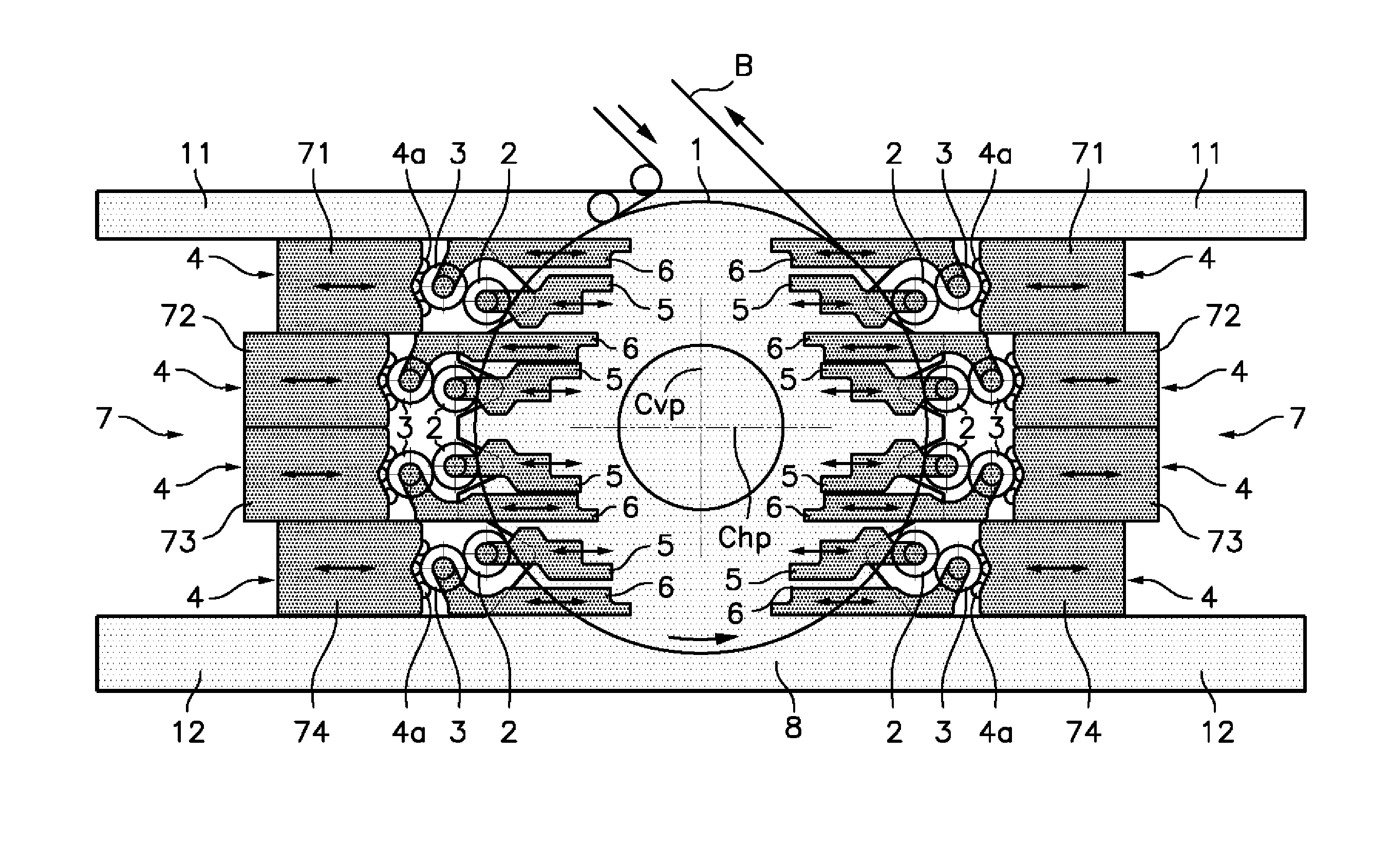
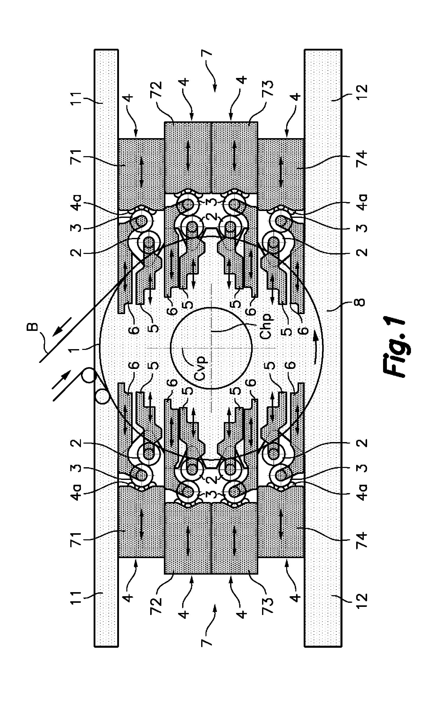
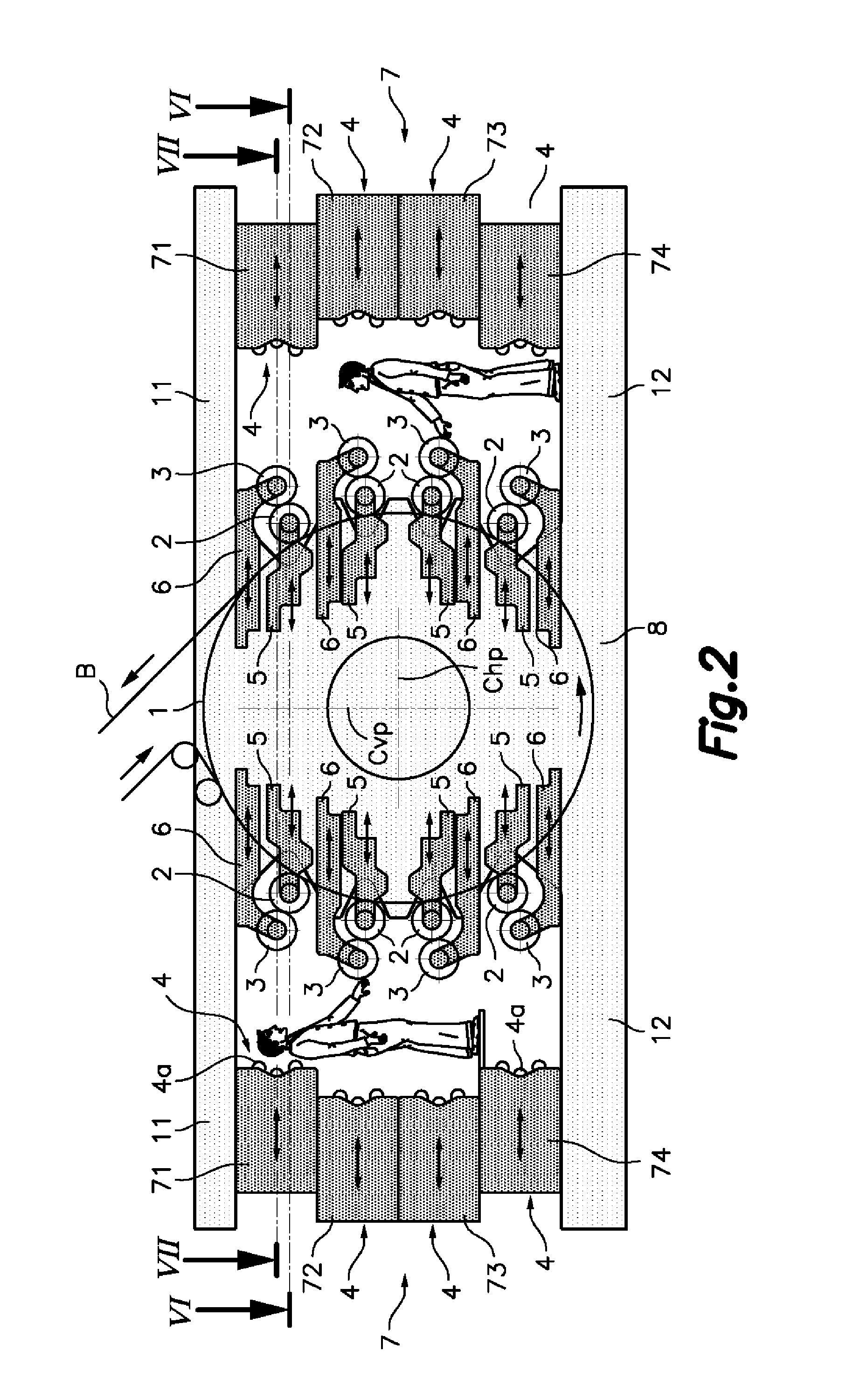
[0045]Referring first to FIGS. 1 and 2, there is shown an offset printing machine according to an exemplary embodiment of the present invention. The offset printing machine comprises a main frame 8 supporting a rotatable central impression cylinder 1 on which a web printable substrate B is supported and a plurality of printing stations arranged around said central impression cylinder 1. In operation, the central impression cylinder 1 rotates in the direction indicated by an arrow (counter clockwise in the Figures) and the web printable substrate B moves in the direction indicated with arrows as the central impression cylinder 1 rotates and comes in contact with the central impression cylinder 1 at a web inlet side thereof (left side in the Figures) and leaves the central impression cylinder 1 at an opposite web outlet side thereof (right side in the Figures). More specifically, in the illustrated exemplary embodiment there are four of said printing stations arranged at said web inle...


PUM


Abstract

The printing machine comprises a central impression cylinder (1) on which a web printable substrate (B) is supported and a plurality of printing stations arranged around the central impression cylinder (1). Each printing station comprises a blanket cylinder (2) of variable diameter, a plate cylinder (3) of variable diameter, and an offset inking unit (4). Said blanket cylinder (2), plate cylinder (3) and offset inking unit (4) are individually movable between respective withdraw positions and respective multiple working positions for different diameters of the blanket and plate cylinders (2, 3). At least one of said printing stations has the axis of the blanket cylinder (2) and the axis of the plate cylinder (3) comprised in an inclined first plane (P1) which does not comprise the axis of the central impression cylinder (1) at any of said multiple working positions for different diameters of the blanket and plate cylinders (2, 3).

Description

TECHNICAL FIELD[0001]The present inventions relates to a web offset printing machine having a central impression cylinder and a plurality of printing stations arranged around said central impression cylinder, where the printing stations can be adjusted to work with printing cylinders of different diameters allowing variable format, in other words variable repeat lengths.BACKGROUND OF THE INVENTION[0002]Flexographic and gravure printing were the traditional and long-time processes for printing on flexible substrates for packaging, labels, bags and the like. In the recent years, volumes of individual printing jobs went down from over multiple 100.000 of copies to several 1000 copies. This tendency is growing and is driven by the need to prevent dead capital in printed stock and by the need for quick reaction on events in the form of action packs and the higher degree of diversity of packed products. These new demands from the market made clear that flexographic and gravure printing ha...

Claims


Application Information

Patent Timeline
Patent Type & Authority Applications(United States)
IPC IPC(8): B41F13/193
CPCB41F13/193B41F7/10B41F13/0024B41F13/20B41F13/30B41F13/44B41F3/54B41F5/24
Inventor VAN DER MEULEN, MICHIELPUIG VILA, JORDISCHOONMAN, ADELBERT LUCASPUIGDEMONT, LLUISRUIZ SUESA, LUIS ANTONIO
Owner COMEXI GRP IND
Why Eureka
Try Eureka