Apparatus and method of interconnecting a plurality of solar cells

a solar cell and electrical interconnection technology, applied in the direction of soldering apparatus, manufacturing tools,auxillary welding devices, etc., can solve the problems of increasing the likelihood of cracks forming in the solar cell or the the cracking or even breaking of the solar cell during the cell interconnection process, and the formation of mechanical stress between. to achieve the effect of maximizing energy and power efficiency

Inactive Publication Date: 2013-10-24
ASM TECH SINGAPORE PTE LTD
View PDF8 Cites 10 Cited by
  • Summary
  • Abstract
  • Description
  • Claims
  • Application Information

AI Technical Summary

Benefits of technology

[0008]By having the roller operative to roll along the solar cell to press the electrical conductor against the electrical contact of the solar cell, the electrical conductor may be continuously and uniformly soldered to the solar cell. Additionally, a free end of the electrical conductor that has not been soldered to the electrical contact of the solar cell is allowed to expand upon heating by the heat-generating device. This accordingly minimizes the effect of the thermal mismatch in the CTE between the electrical conductor and the electrical contact of the solar cell, and advantageously improves the soldering quality.
[0010]For example, the heat-generating device may comprise an inductor loop for generating a magnetic field to induce an electrical current in the electrical contact of the solar cell to thereby generate heat for soldering the electrical conductor thereto. The inductor loop may be arranged around the roller. In this way, the magnetic field generated by the inductor loop may be directed axially on the electrical conductor and the electrical contact of the solar cell for soldering. Further, the roller may comprise diamagnetic material for concentrating the magnetic field generated by the inductor loop within a space enclosed by the inductor loop. This concentrates the magnetic field generated by the inductor loop within a space enclosed by the inductor loop, and advantageously maximizes energy and power efficiency.

Problems solved by technology

If the process is not carefully controlled, the likelihood of cracks forming in the solar cells or the solar cells breaking would increase.
This is because thermal mismatch in the Coefficient of Thermal Expansion (‘CTE’) between the conductive ribbons and the busbars results in mechanical stress forming between them.
Consequently, if the solder solidification point, the cooling speed, the material cross-sections and the ductility of the electrical conductor are not carefully chosen, the solar cell may crack or even break during the cell interconnection process.
Improper cell interconnection may also affect solar energy to electrical energy conversion of the solar array.

Method used


Image

  • Apparatus and method of interconnecting a plurality of solar cells
  • Apparatus and method of interconnecting a plurality of solar cells
  • Apparatus and method of interconnecting a plurality of solar cells

Examples


Embodiment Construction

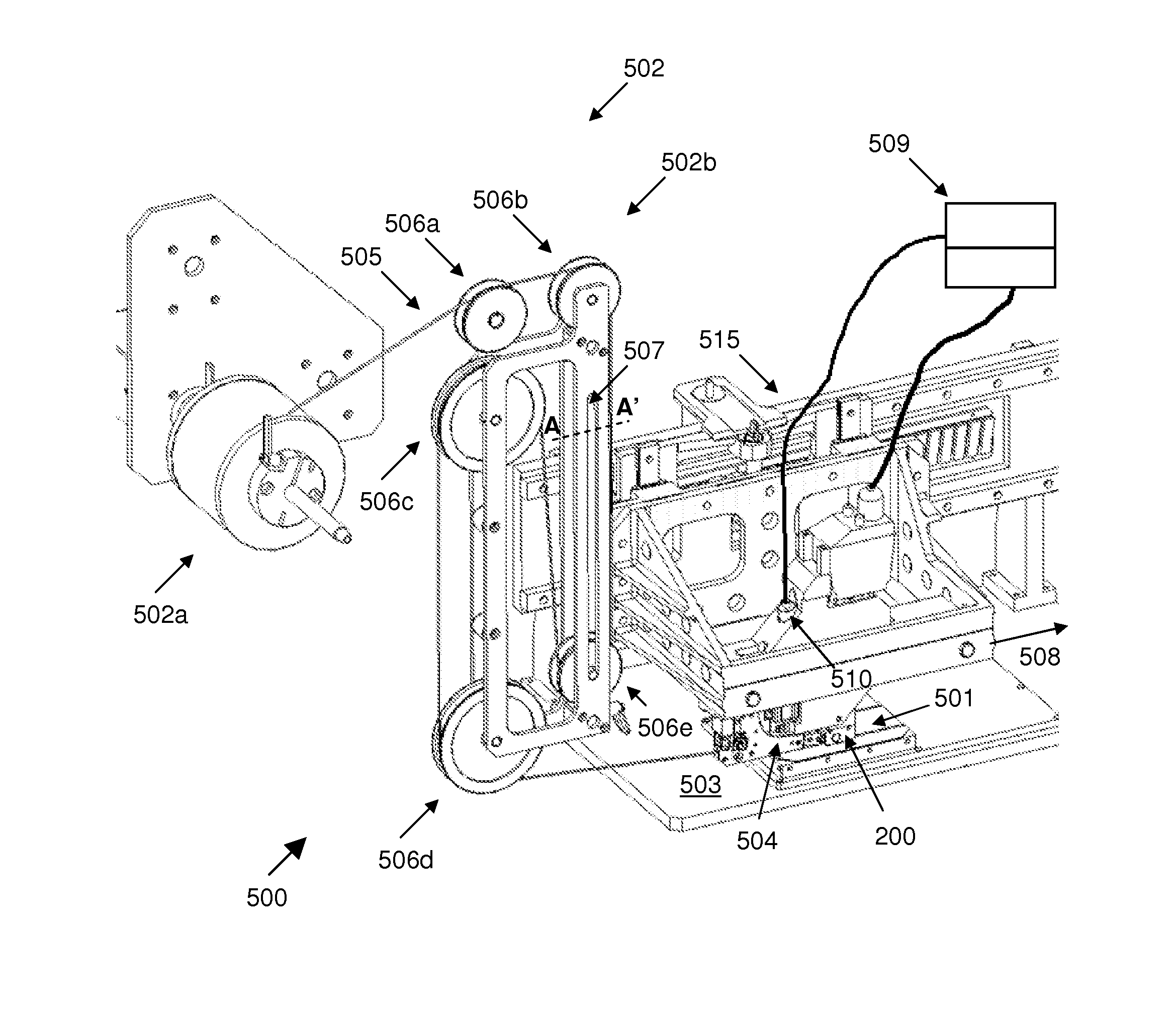
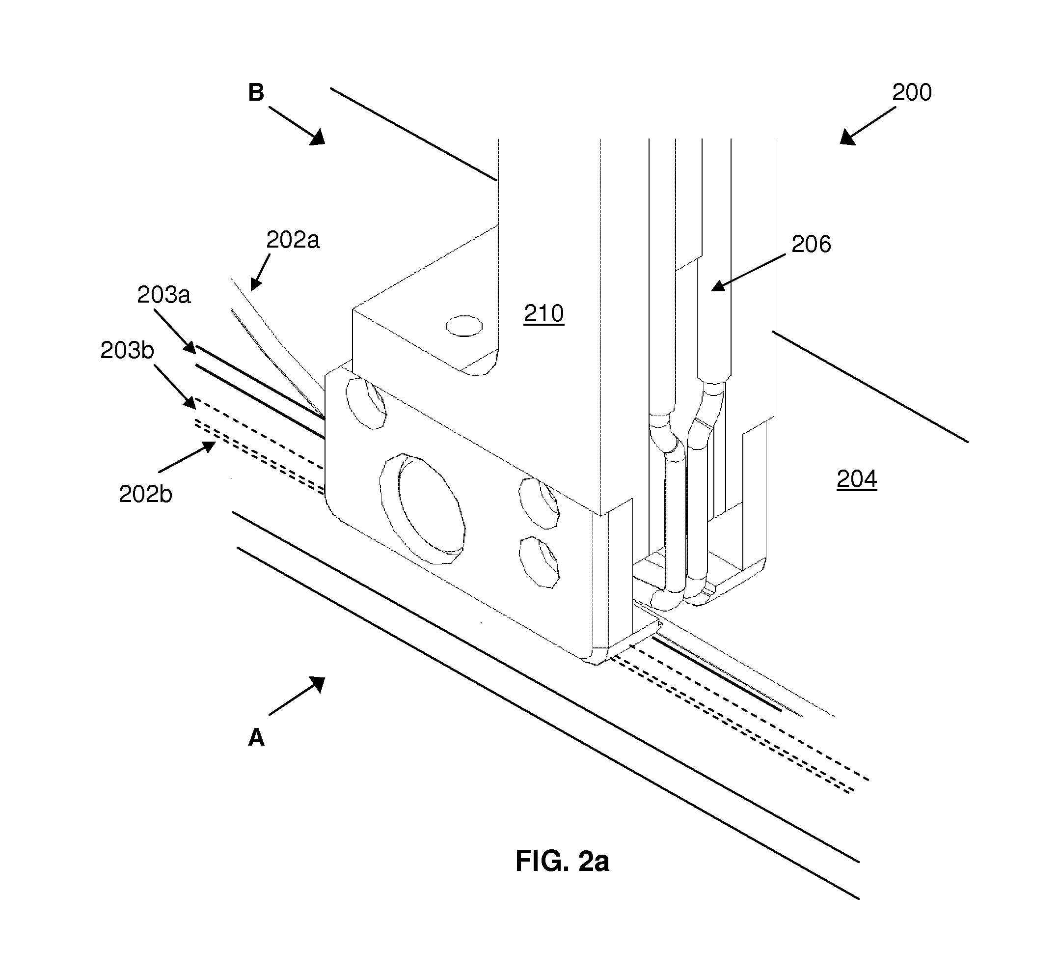
[0022]FIG. 2a is an isometric view of a soldering device 200 according to a first preferred embodiment of the present invention, while FIG. 2b and FIG. 2c are respective side views of the soldering device 200 when viewed along directions A and B shown in FIG. 2a.

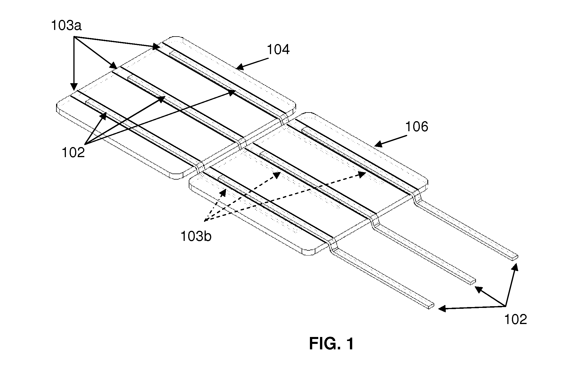
[0023]In particular, the soldering device 200 is configured to solder an electrical conductor (shown as conductive ribbons 202a, 202b) to an electrical contact (e.g. a busbar 203a on a front surface and a busbar 203b on a back surface) of a solar cell 204, so as to electrically interconnect the solar cell 204 with one or more other solar cells (not shown) to form a string.

[0024]The soldering device 200 comprises: i) a heat-generating device (shown as an inductor loop 206) for providing heat to solder the conductive ribbons 202a, 202b to the busbars 203a, 203b of the solar cell 204; ii) a roller (shown as a wheel 208 in FIG. 2b) installed within the inductor loop 206 for rolling along the solar cell 204 to press the conducti...


PUM

PropertyMeasurementUnit
angleaaaaaaaaaa
distanceaaaaaaaaaa
widthaaaaaaaaaa

Abstract

Disclosed is an apparatus for electrically interconnecting a plurality of solar cells. The apparatus comprises: i) a roller operative to roll along a solar cell to press an electrical conductor against an electrical contact of the solar cell, the electrical conductor being for electrically interconnecting the solar cell with one or more other solar cells; and ii) a heat-generating device arranged and configured to provide heat for soldering the electrical conductor to the electrical contact of the solar cell while the roller is pressing the electrical conductor against the electrical contact of the solar cell. A method of electrically interconnecting a plurality of solar cells, and a mechanism for laying and soldering an electrical conductor onto a solar cell, are also disclosed.

Description

FIELD OF THE PRESENT INVENTION[0001]This invention relates to an apparatus and method of electrically interconnecting a plurality of solar cells, in which an electrical conductor is used to electrically interconnect a solar cell with one or more other solar cells.BACKGROUND OF THE INVENTION[0002]Solar cells are electrical devices that convert light energy into electrical energy based on the photovoltaic (‘PV’) effect. Each solar cell is fabricated from a solar wafer belonging to either a mono-crystalline or multi-crystalline type. A fabricated solar cell normally includes metallic front and back contacts known as busbars' that may be made up of silver and / or silver with aluminum. The solar cell is then interconnected with a number of other solar cells in series to form a string, and finally, a solar cell array formed by interconnecting a number of parallel strings together.[0003]FIG. 1 is an isometric view of two solar cells 104, 106 electrically interconnected to each other using c...

Claims


Application Information

Patent Timeline
Patent Type & Authority Applications(United States)
IPC IPC(8): B23K1/002B23K3/08B23K26/20B23K3/047B23K1/20B23K31/02B23K3/04
CPCH01L31/188B23K1/0016B23K1/002B23K1/0056B23K3/0475B23K3/087Y02E10/50
Inventor TAN, LIAN HOKTU, WEN GEYANG, PAN
Owner ASM TECH SINGAPORE PTE LTD
Why Eureka
Try Eureka