Variable transmittance optical devices

a technology of optical filters and transmittance, applied in static indicating devices, instruments, conductive pattern formation, etc., can solve the problems of high voltage or bulky power sources that are not suitable for retrofitting wiring, and the power demand may increase with the size of the device, so as to reduce solar heat gain and reduce cooling loads in buildings. , the effect of reducing power demands

Active Publication Date: 2013-10-24
SOLUTIA CANADA INC
View PDF6 Cites 218 Cited by
  • Summary
  • Abstract
  • Description
  • Claims
  • Application Information

AI Technical Summary

Benefits of technology

[0024]Aspects of the invention may be advantageous in reducing solar heat gain and / or reducing cooling loads in buildings, vehicles and transit systems. Aspect of the invention may be useful as variable glare- or light-reducing lenses or visors of opthalmic devices. The darkening response to UV light does not require power input, and the electrochromic fading is effected with very low power demands that may be met by small, portable or wearable, energy harvesting power sources.

Problems solved by technology

Such existing power source and wiring may be used in this manner, and may not be inconvenient when a building is designed to accommodate windows or screens comprising such devices, it may necessitate an undesired amount of routing of electrical cables to the device, or cumbersome retrofitting of wiring to accommodate optical filters put in place after a building is constructed.
Thus, devices with a need for high voltage or a bulky power source may not be suitable.
Some electrochromic devices require continuous power to maintain the dark or faded state, and the power demand may increase with increasing size of the device, particularly windows.
For a solar-powered window, a photovoltaic power source with a surface area of sufficient size to meet the device's power requirement may be of an impractical size, and / or prohibitively expensive.
If the photovoltaic power source is on a frame or pane of a window or lens, it may interfere with aspects such as window viewability.
As photovoltaic power sources are dependent on the available amount of incident light, some lighting conditions may not consistently provide sufficient incident light to generate sufficient power for operation.
Finally, even with self-contained photovoltaic power sources, the solutions identified in the past may not provide an adequate means for retrofitting existing buildings with smart window technology.

Method used


Image

  • Variable transmittance optical devices
  • Variable transmittance optical devices
  • Variable transmittance optical devices

Examples


example 1

Preparation of Selected Hybrid P / E Compounds

S001 and S002 were Prepared as Described in U.S. Pat. No. 7,777,055.

Synthesis of S042

[0199]

Synthesis of 3-bromo-2,5-bis(4-(tert-butyl)phenyl)thiophene: (30)

[0200]Sodium carbonate monohydrate (58.0 g, 468 mmol) was dissolved in water (500 mL) and a solution of 4-(tert-butyl)-phenylboronic acid (40.0 g) and 2,3,5-tribromothiophene (30.0 g, 94 mmol) in THF (500 mL) was added, and deoxygenated by bubbling with argon. Pd(PPh3)4 (5.0 g, 4.30 mmol) was added and the mixture refluxed for 24 h. The mixture was cooled and the aqueous phase separated and extracted with EtOAc. Organic fractions were combined washed with water (500 mL) and dried over MgSO4. The solvent was evaporated and the crude product washed in MeOH, filtered and dried overnight to afford a light yellow, powdery solid (35.46 g, 89%).

Synthesis of S042

(3,3′-(perfluorocyclopent-1-ene-1,2-diyl)bis(2,5-bis(4-(tert-butyl)phenyl)thiophene)

[0201]A solution of (30) in anhydrous THF / ether co...

example 2

Preparation of Variable Transmittance Optical Filters

[0208]Method A:

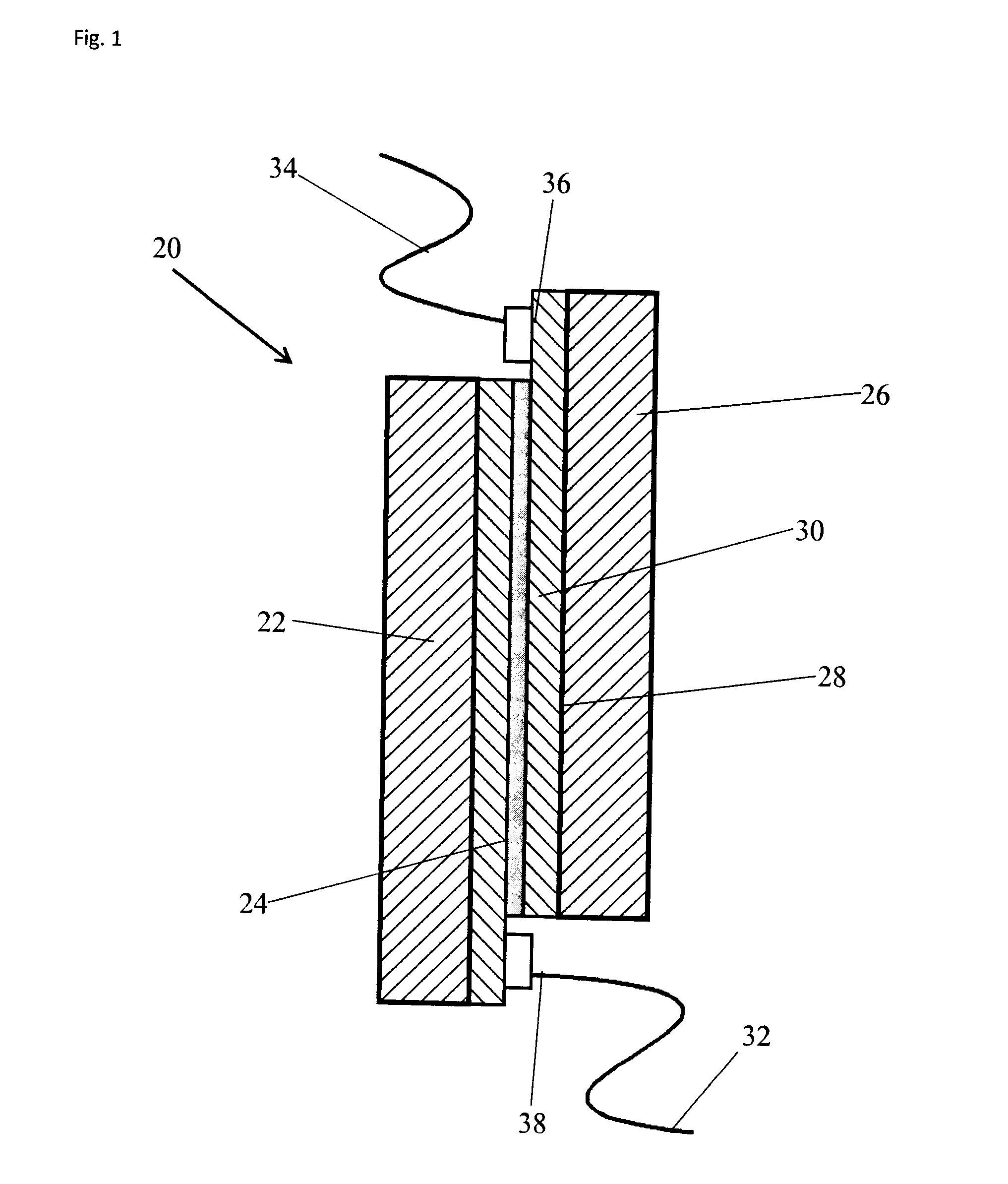
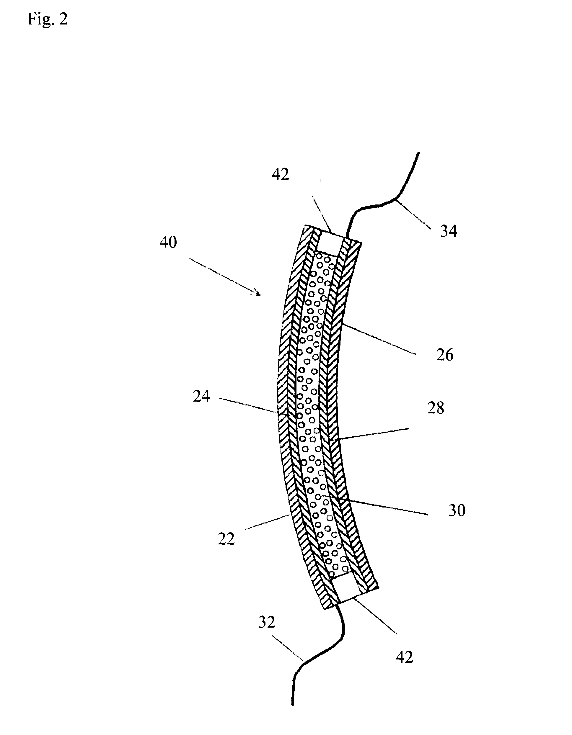
[0209]An ITO-coated PET substrate having a thickness of 7 mil (˜178 microns) and a sheet resistance of 50 ohms / square (OC50, made by CP Films) is cut into two 15 cm×15 cm sheets. The substrate may be cleaned before use, and is temporarily laminated to glass plates to facilitate handling. Steel spacers are positioned at the perimeter of the PET, to set the gap for the final pressed device (from 20-70 microns). A volume of switching material (below, heated to facilitate dispensing), is placed on the PET to completely fill the gap between the PET sheets when the device is pressed. A second piece of glass-backed PET is placed on top, so that the PET sheets overlap such that there is some ITO coating exposed, to act as the external electrical contacts. The sandwich (glass-PET-switching material-PET-glass) is placed in the center of a press platens (heated to 45° C.). Pressure greater than 160 psi is applied to the filter...

example 3

Preparation of the Switching Material

[0212]The switching material was formulated to demonstrate how the components of the formulation can be varied. These formulations can be readily adapted to a desired application by a worker skilled in the art, by replacing the listed ingredients with one or more other ingredients in accordance with embodiments of the present invention. Table 1 sets out formulations for switching material that may be used in a device according to various embodiments of the invention. Compounds that may be used in the formulations include those according to Formulae IA / IB, and those illustrated herein. In some examples, the compound used in a formulation may be S001, or a derivative thereof having a functional groups on one or more of the four peripheral thiophene rings; or S002, or a derivative thereof having a functional group on one or more of the peripheral phenyl rings; or S042, or a derivative thereof having another functional group on one or more of the per...


PUM

PropertyMeasurementUnit
wavelengthsaaaaaaaaaa

Abstract

A self-powered variable transmittance optical device, such as a smart window or other device, and associated method are provided. The device comprises one or more transparent substrates, with a switching material disposed thereon or therebetween. The switching material may be a hybrid photochromic / electrochromic material capable of transitioning from a first transmittance state to a second transmittance state with application of electricity, and from second state to first state due to another stimulus, such as UV radiation. Electrodes are coupled to the switching material for applying electricity. An electrical system provides for controllable application of the electricity, and may store energy. Energy is provided by an energy-harvesting power source such as a solar cell or other photovoltaic source, or array thereof, or another device for harvesting vibrational or thermal energy. Energy harvesting, energy storage capacity and / or switching material may be configured to provide at least a predetermined level of device operability.

Description

RELATED CASES[0001]This application claims the benefit of U.S. Provisional Application No. 61 / 423,524 filed Dec. 15, 2010, which is incorporated herein by reference in its entirety.FIELD OF THE INVENTION[0002]The present invention relates generally to variable transmittance optical filters and devices comprising such filters. The devices may further comprise a power source.BACKGROUND OF THE INVENTION[0003]Optical filters have been used in glazings in window technology to control the flow of light and heat through the glazing. Such filters may be used on any sort of window, including those in buildings, vehicles, aircraft, spacecraft, ships or the like. Optical filters have also been used to regulate lighting and heating levels, for glare reduction, and energy load management. As an example, buildings consume over one third of all energy and over two-thirds of the electricity used in the United States, and are responsible for about one third of all greenhouse gas (GHG) emissions, as ...

Claims


Application Information

Patent Timeline
Patent Type & Authority Applications(United States)
IPC IPC(8): G02F1/163G02F1/01G02F1/1516
CPCG02F1/163G02F1/0102B60J3/04G02C7/101G02F1/153G02F2202/14Y10T29/49155G02B5/23G02B5/208G02F1/0126G02C7/102G02F2201/086G09G3/34G02F1/1516G02F1/15165G09G3/38G02F1/157
Inventor LAM, DUHANEBRANDA, NEIL ROBINSMIT, MATTHEW PAULVON HAHN, PETER ALEXANDER
Owner SOLUTIA CANADA INC
Why Eureka
Try Eureka