Heat exchange system

a heat exchange system and heat exchange technology, applied in the field of heat exchange systems, can solve the problems of unfavorable heat exchange, slow rise in the temperature of the engine coolant in comparison to a normal vehicle, and inability to heat the blowing air of the heater core, so as to reduce the discharge capacity of the compressor, reduce the heat load of the heat pump cycle, and reduce the heat load of the evaporator.

Active Publication Date: 2013-10-31
DENSO CORP
View PDF8 Cites 15 Cited by
  • Summary
  • Abstract
  • Description
  • Claims
  • Application Information

AI Technical Summary

Benefits of technology

[0094]A heat exchange system according to a twenty-eighth aspect of the present disclosure may be applied to an air conditioner that cools a blowing air to be blown into an air conditioning object space by performing heat exchange between the blowing air and a refrigerant at an evaporator of a heat pump cycle. In this case, the first fluid is a heat medium that is heated by heat possessed by a discharged refrigerant discharged from the compressor of the heat pump cycle, the heat radiation amount adjustment unit may decrease a heat load of the heat pump cycle by changing a ratio of an inside air and an outside air, in order to have a greater amount of the inside air than the outside air to be circulated or introduced into the

Problems solved by technology

However, in a hybrid vehicle and in an idle-stop vehicle (i.e., an engine-stop function equipped vehicle), temperature of an engine coolant is slow to rise in comparison to a normal vehicle that always operates the engine, due to the stopping of the internal combustion engine during the travel of the vehicle or at a time of a temporary stop of the vehicle for the purpose of improving the fuel mileage.
Therefore, if the heat exchange system of the patent document 1 is installed in the hybrid/idle-stop vehicle and an engine coolant is used as a brine in the heater core, the heating heat exchanger may be able to heat the blowing air, but the heater core may not be capable of heating the blowing air when a temperature of the coolant is lower than temperature of the discharged refrigerant.
Instead, there may be a case that the blowing air having already been heated by the heating heat exchanger dissipates heat to the coolant, which is an unwanted exchange of heat.
Further, if the heat exchange system of the patent document 2 is installed in the hybrid/idle-stop vehicle, not only the heater core but also the heating heat exchanger may not be capable of su

Method used


Image

  • Heat exchange system
  • Heat exchange system
  • Heat exchange system

Examples


first embodiment

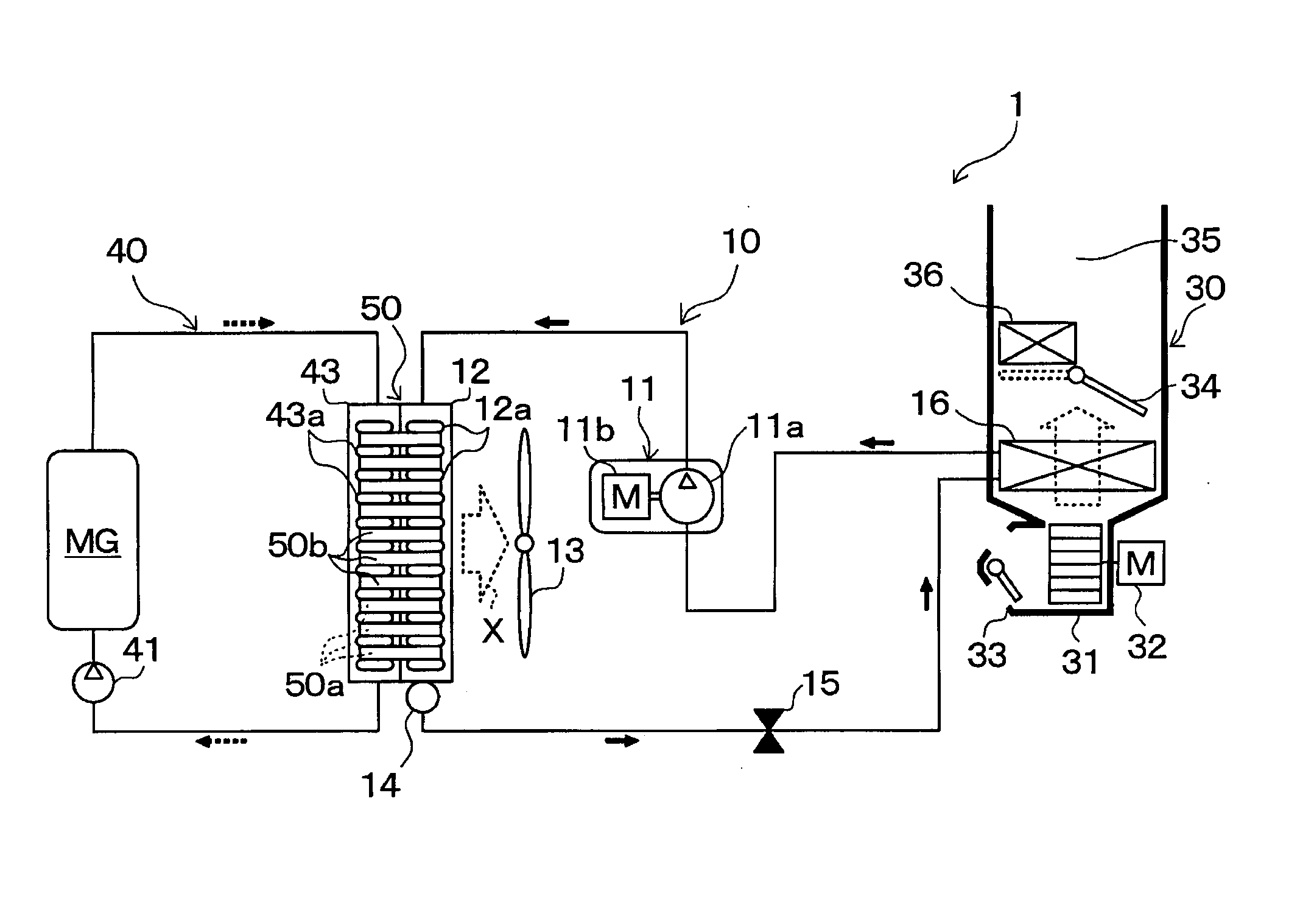
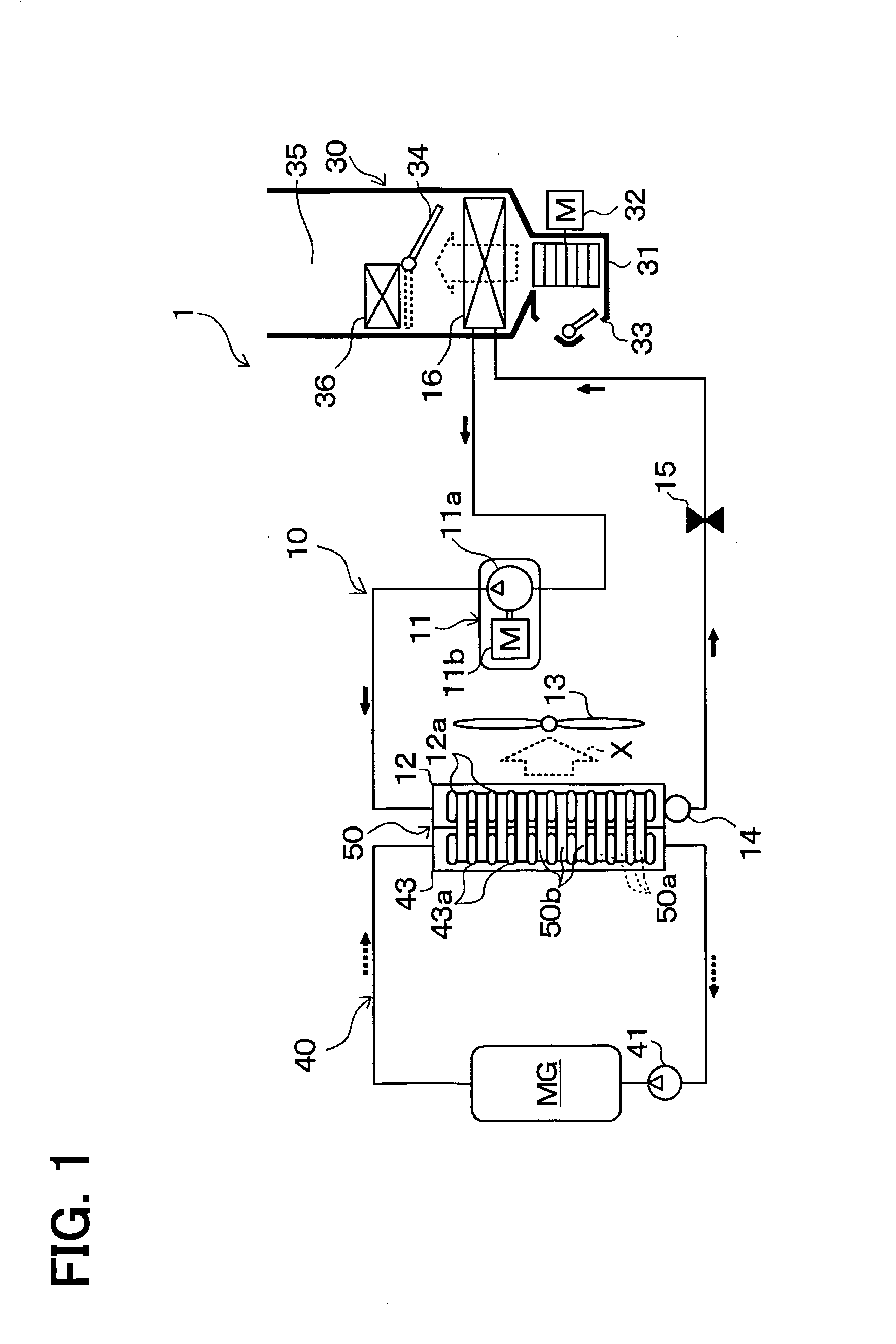
[0115]With reference to FIG. 1 to FIG. 8(b), the first embodiment of the present disclosure will be described. In the present embodiment, a heat exchange system of the present disclosure is implemented to realize a vehicular air conditioner 1 used in a hybrid vehicle which derives a driving power for the travel of the vehicle from an internal combustion engine (i.e., an engine) and from an electric motor MG. FIG. 1 is a schematic diagram of a total configuration of the vehicular air conditioner 1 of the present embodiment.

[0116]The hybrid vehicle can perform switching between two traveling states, i.e., one traveling state in which the vehicle travels obtaining the driving force from both of the engine and the electric motor MG for traveling by operating or stopping the engine according to a traveling load on the vehicle or the like and the other traveling state in which the vehicle travels obtaining the driving force only from the electric motor MG for traveling by stopping the eng...

second embodiment

[0211]In the present embodiment, as shown in FIG. 9, a configuration of the coolant circulation circuit 40 is changed from the first embodiment. More practically, the coolant circulation circuit 40 has, in addition to the coolant pump 41 and the radiator 43, an electric-type three-way valve 42 and a bypass passage 44 that bypasses a flow of the coolant around the radiator 43. Further, in FIG. 9, like parts have like numbers as the first embodiment. Such numbering also applies to the other drawings.

[0212]The three-way valve 42 switches two circuits, that is, a heat medium circuit that connects an inlet side of the coolant pump 41 and an outlet side of the radiator 43 to introduce the coolant flowing into the radiator 43 and let detour around the radiator 43, and a heat medium circuit that connects an inlet side of the coolant pump 41 and an outlet side of the bypass passage 44 to bypass the coolant around the radiator 43. Further, the operation of the three-way valve 42 is controlled...

third embodiment

[0219]In the present embodiment, as shown in FIG. 10, a configuration of the heat pump cycle 10 is changed from the second embodiment. The heat pump cycle 10 of the present embodiment has a switchable refrigerant circuit that is switchable between a heating operation and a cooling operation, i.e., the heating operation for heating a blowing air that is blown into the vehicle compartment (i.e., “heating mode”) and the cooling operation for cooling a blowing air that is blown into the vehicle compartment (i.e., “cooling mode”).

[0220]More practically, a refrigerant inlet side of an interior condenser 37 is connected to a refrigerant discharge port of the compressor 11 in the present embodiment. The interior condenser 37 is a heater (i.e., a heat exchanger for heating), disposed in the casing 31 of an interior air conditioning unit 30 of the vehicular air conditioner 1, for heat exchange between a high-temperature high-pressure refrigerant flowing therein (i.e., in the casing 31) and a ...


PUM


Abstract

A heat exchange system for realizing an adequate heat exchange among a plural type of fluids uses a refrigerant radiator and a radiator which are combined to have one unit for enabling heat exchange between a refrigerant and a coolant, and decreases an inflow amount of the coolant flowing into the radiator when coolant temperature of the coolant flowing into the radiator is equal to or higher than a second standard temperature, which is set to be lower than a temperature of the refrigerant flowing into the refrigerant radiator, and is equal to or lower than a predetermined first standard temperature. In such manner, heat from the refrigerant is effectively transferred to an outside air by reducing an unwanted heat exchange between the refrigerant and the outside air.

Description

CROSS REFERENCE TO RELATED APPLICATION[0001]This application is based on and claims the benefit of priority of Japanese Patent Applications No. 2010-284830 filed on Dec. 21, 2010, and No. 2011-272273 filed on Dec. 13, 2011, the disclosures of which are incorporated herein by reference.TECHNICAL FIELD[0002]The present disclosure generally relates to a heat exchange system in which heat is exchanged among a plurality of fluids.BACKGROUND[0003]Conventionally, as disclosed in Japanese patent documents 1 and 2, a vehicular air conditioner heats air, i.e., a blowing air to be sent into a vehicle compartment, by exchanging heat between the air (i.e., a third fluid) and a discharged refrigerant (i.e., a first fluid) discharged from a compressor. Further, the above documents 1, 2 further disclose a configuration that the vehicular air conditioner heats the blowing air by heat exchange between the blowing air and a heat medium that is different from the discharged refrigerant (i.e., a second ...

Claims


Application Information

Patent Timeline
IPC IPC(8): B60H1/00
CPCB60H1/00335B60H1/00735B60H1/00328B60H1/00342B60H1/00921F28D1/0316F28D1/035F28D1/0435F28D1/05391
Inventor KATOH, YOSHIKIINABA, ATSUSHIITOH, SATOSHISHIMOYA, MASAHIRO
Owner DENSO CORP
Why Eureka
Try Eureka