
Unitary heat pump air conditioner

a heat pump and air conditioner technology, applied in heat pumps, lighting and heating apparatus, laminated elements, etc., can solve the problems of reducing the efficiency of the system, and affecting the comfort of passengers, so as to improve the driving range, improve the efficiency of the system, and achieve optimal operating temperature

Inactive Publication Date: 2013-10-31
MAHLE INT GMBH
View PDF15 Cites 46 Cited by
  • Summary
  • Abstract
  • Description
  • Claims
  • Application Information

AI Technical Summary

Benefits of technology

The Unitary HPAC system provides supplemental heat without reversing the refrigerant cycle, improving electric driving range by minimizing electric current usage and efficiently using waste heat, while being compact enough for easy installation in various vehicle compartments.

Problems solved by technology

With the advent of greater efficiency internal combustion engines, hybrid vehicles having smaller internal combustion engines, and especially electrically driven vehicles, the amount of thermal energy available to provide comfort to occupants in the passenger compartment may not be adequate.
One disadvantage to operating the air-conditioning system in heat pump mode, since the low pressure side of the system when used in air conditioning mode would become the high pressure side when used in heat pump mode, is the increase in system complexity due to the requirement of having to reinforce the refrigerant plumbing throughout the system by using thicker gage tubing and fittings.
Another known disadvantage of operating the system in heat pump mode is that in cooler climates, as the surface temperature of the condenser drop below 32° F., any moisture condensed on the surface of the condenser is subject to freezing, therefore potentially reduces the system's efficiency or even damage the condenser.
In the coldest of climates, it is known that operating the air-conditioning system in heat pump mode is ineffective; therefore, additional electric heaters are required.
However, for hybrid and electrical vehicles, electrical heaters represent an increased current draw that significantly reduces the electric drive range.

Method used


Image

  • Unitary heat pump air conditioner
  • Unitary heat pump air conditioner
  • Unitary heat pump air conditioner

Examples


Embodiment Construction

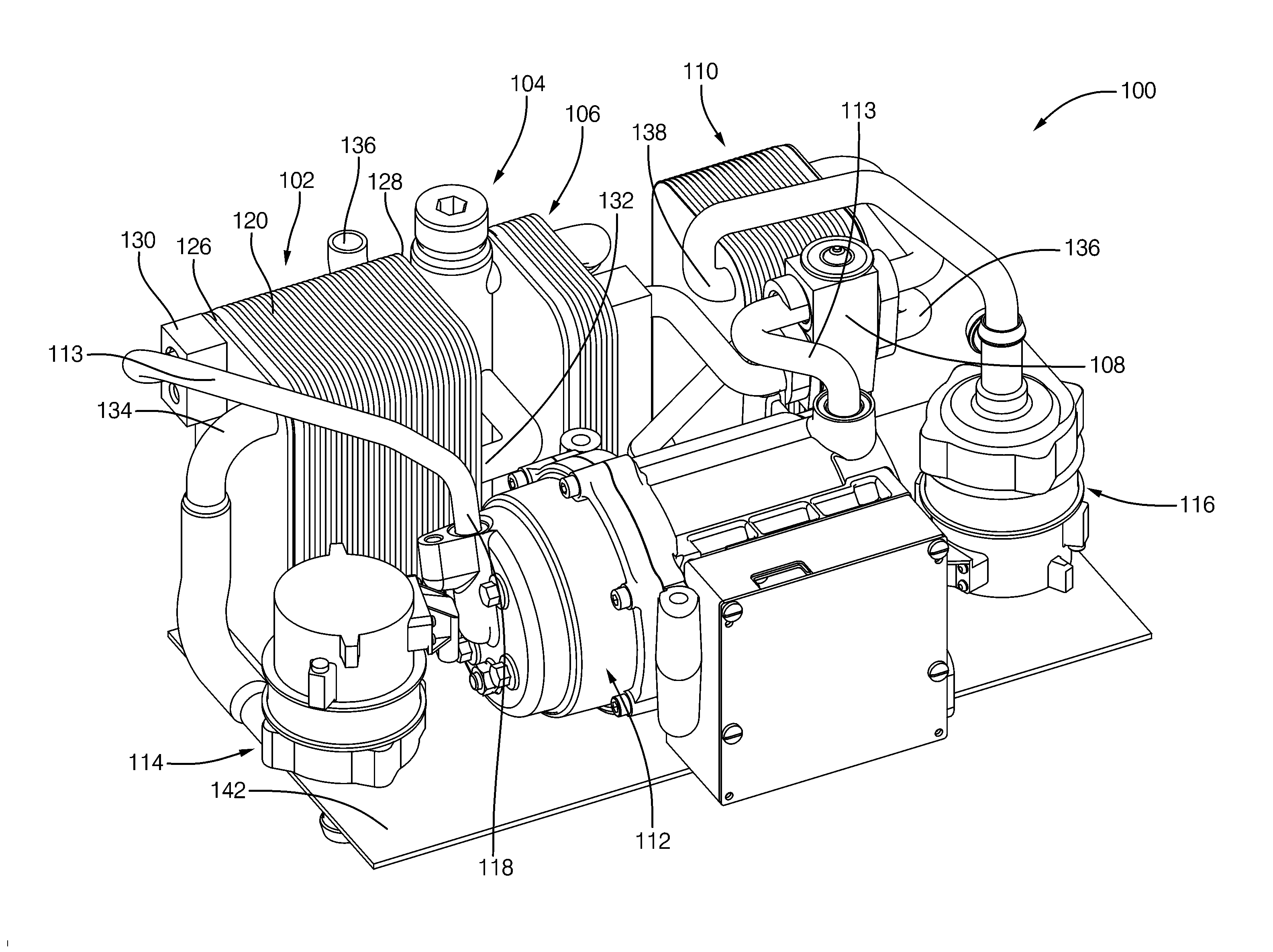
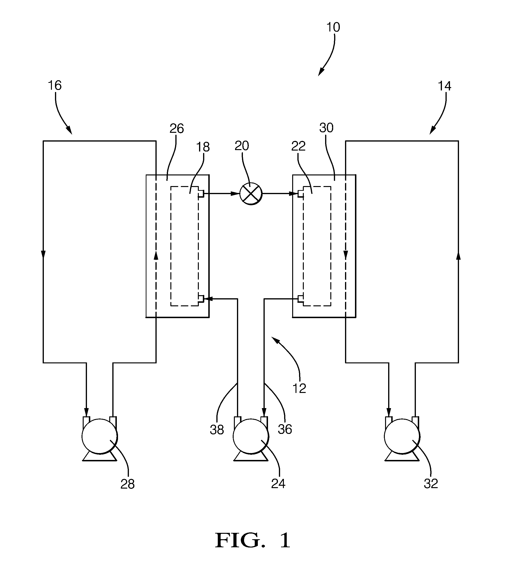
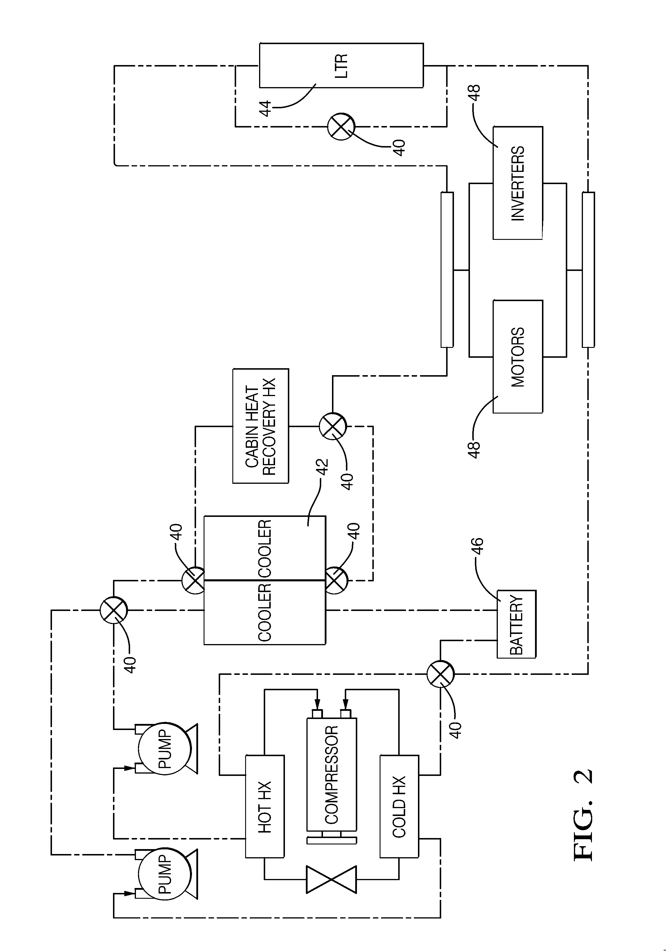
[0015]Referring to FIGS. 1 through FIG. 4 is a Unitary Heat Pump Air Conditioner System (Unitary HPAC System) and an embodiment of a Unitary HPAC for use in a motor vehicle. The motor vehicle may be that of one with an internal combustion engine, a hybrid vehicle having both an internal combustion engine and an electric drive, or that of an electric vehicle having an electric drive. The Unitary HPAC System is a compact hermetically sealed system that improves the overall efficiency of the heating system and also provides cooling system to the motor vehicle. In hybrid and electric vehicles, the Unitary HPAC improves the driving ranges in cold climates by minimizing the use of electric current to power electric heaters and providing heat to the battery packs to maintain an optimal operating temperature. The Unitary HPAC system provides a dedicated refrigerant system in which the refrigerant cycle does not need to be reversed in order for the Unitary HPAC system to operate in heat pump...


PUM


Abstract

The disclosure relates to a unitary heat pump air conditioner (Unitary HPAC) that includes a refrigerant loop having a condenser, a refrigerant expansion device, and an evaporator hydraulically connected in series. An electrically driven compressor is provided to circulate a two-phase refrigerant through the refrigerant loop to transfer heat from the evaporator to the condenser. The unitary HPAC also includes a cold side chiller configured to hydraulically connect to a cold side coolant loop and is in thermal communication with the evaporator. The unitary HPAC further includes a hot side chiller configured to hydraulically connect to a hot side coolant loop and is in thermal communication with the condenser. The refrigerant loop transfer heat from the cold side chiller to the hot side chiller, thereby cooling the cold side coolant loop and heating the hot side coolant loop. The components of the unitary HPAC are mounted on a common platform.

Description

CROSS-REFERENCE TO RELATED APPLICATION[0001]This application is a national stage application under 35 U.S.C. 371 of PCT Application No. PCT / US2012 / 025419 having an international filing date of 16 Feb. 2012, which designated the United States, which PCT application claimed the benefit of U.S. Provisional Patent Application Ser. No. 61 / 443,774, filed Feb. 17, 2011, the entire disclosure of each of which are hereby incorporated by reference.TECHNICAL FIELD OF INVENTION[0002]The present invention relates to a heating and air-conditioning system for an automotive vehicle; particularly, to a heat pump air-conditioning system.BACKGROUND OF INVENTION[0003]For the comfort of the occupants in the passenger compartment, motor vehicles typically include dedicated air-conditioning systems and heating systems. The heating system includes a heater core located inside a heating, ventilating, and air conditioning (HVAC) module of the vehicle. The heater core is typically a liquid-to-air heat exchang...

Claims


Application Information

Patent Timeline
Patent Type & Authority Applications(United States)
IPC IPC(8): F25B30/02
CPCF25B30/02F28D9/005F28D9/0093B60H1/00342B60H1/00899B60H2001/00928F25B29/003B60H1/32284B60H1/3229F25B1/00F28F3/08
Inventor KADLE, PRASAD S.ODDI, FREDERICK V.VREELAND, GARY S.WOLFE, IV, EDWARDLEITZEL, LINDSEY L.LIPA, SCOTT B.
Owner MAHLE INT GMBH
Learn More