Power feeding system and power feeding method

a technology of power feeding system and power feeding method, which is applied in the direction of rail devices, transportation and packaging, high-level techniques, etc., can solve the problems of difficult to specify and manage each other

Active Publication Date: 2013-10-31
SEMICON ENERGY LAB CO LTD
View PDF4 Cites 74 Cited by
  • Summary
  • Abstract
  • Description
  • Claims
  • Application Information

AI Technical Summary

Benefits of technology

[0010]However, since power is transmitted using electromagnetic waves in a wireless power feeding system, the power transmission efficiency is likely to be lowered although power can be fed wirelessly.

Problems solved by technology

Further, there is a problem in that it is difficult to specify and manage a power feeding provider which transmits power (a power transmitting side or a power transmitting device) and a power feeding user which receives power (a power receiving side or a power receiving device) or it is difficult for them to specify and manage each other.

Method used


Image

  • Power feeding system and power feeding method
  • Power feeding system and power feeding method
  • Power feeding system and power feeding method

Examples


embodiment 1

[0039]In this embodiment, embodiments of a power feeding system and a power feeding method are described with reference to FIGS. 1A to 1C, FIGS. 2A to 2C, FIGS. 3A to 3C, FIG. 4, and FIG. 5.

[0040]First, a power feeding system which is one embodiment of the present invention is described below with reference to FIGS. 1A to 1C, FIGS. 2A to 2C, and FIGS. 3A to 3C.

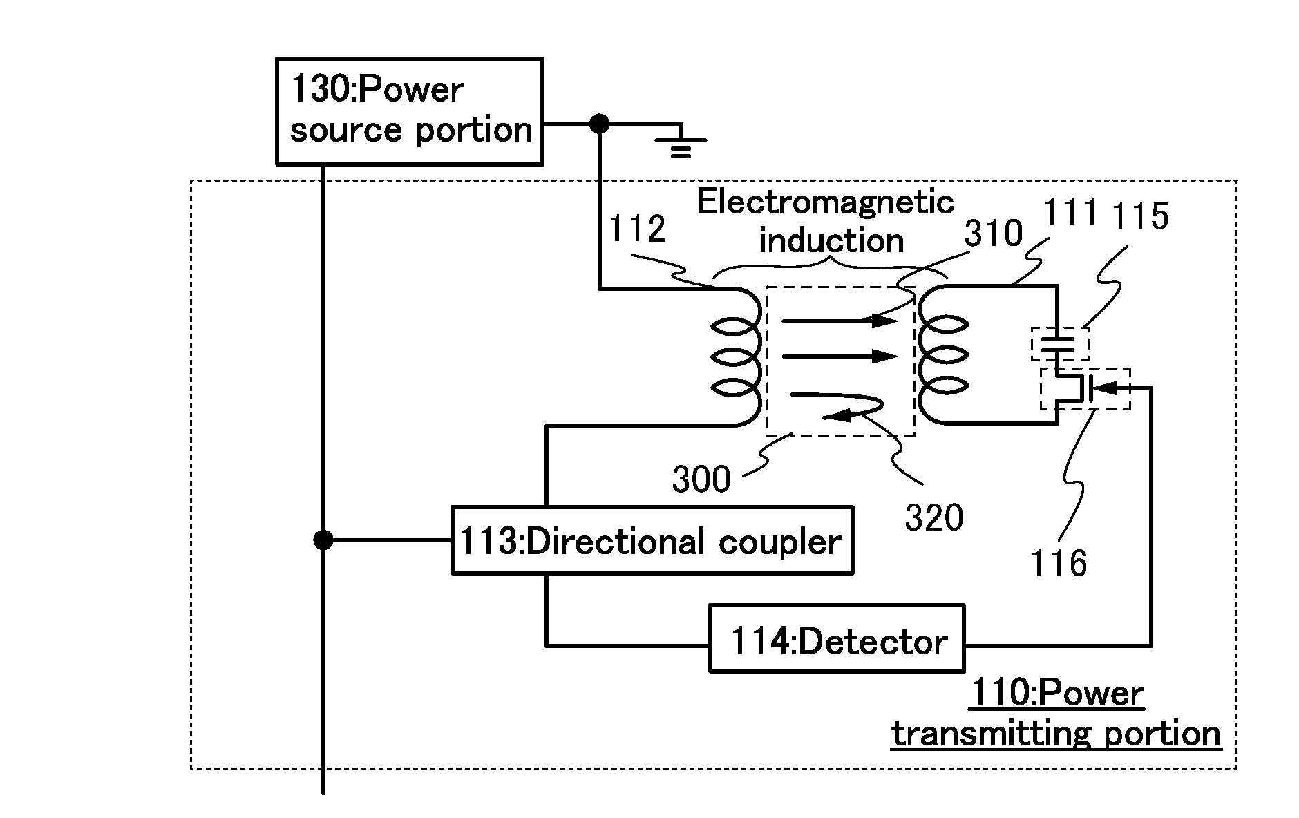
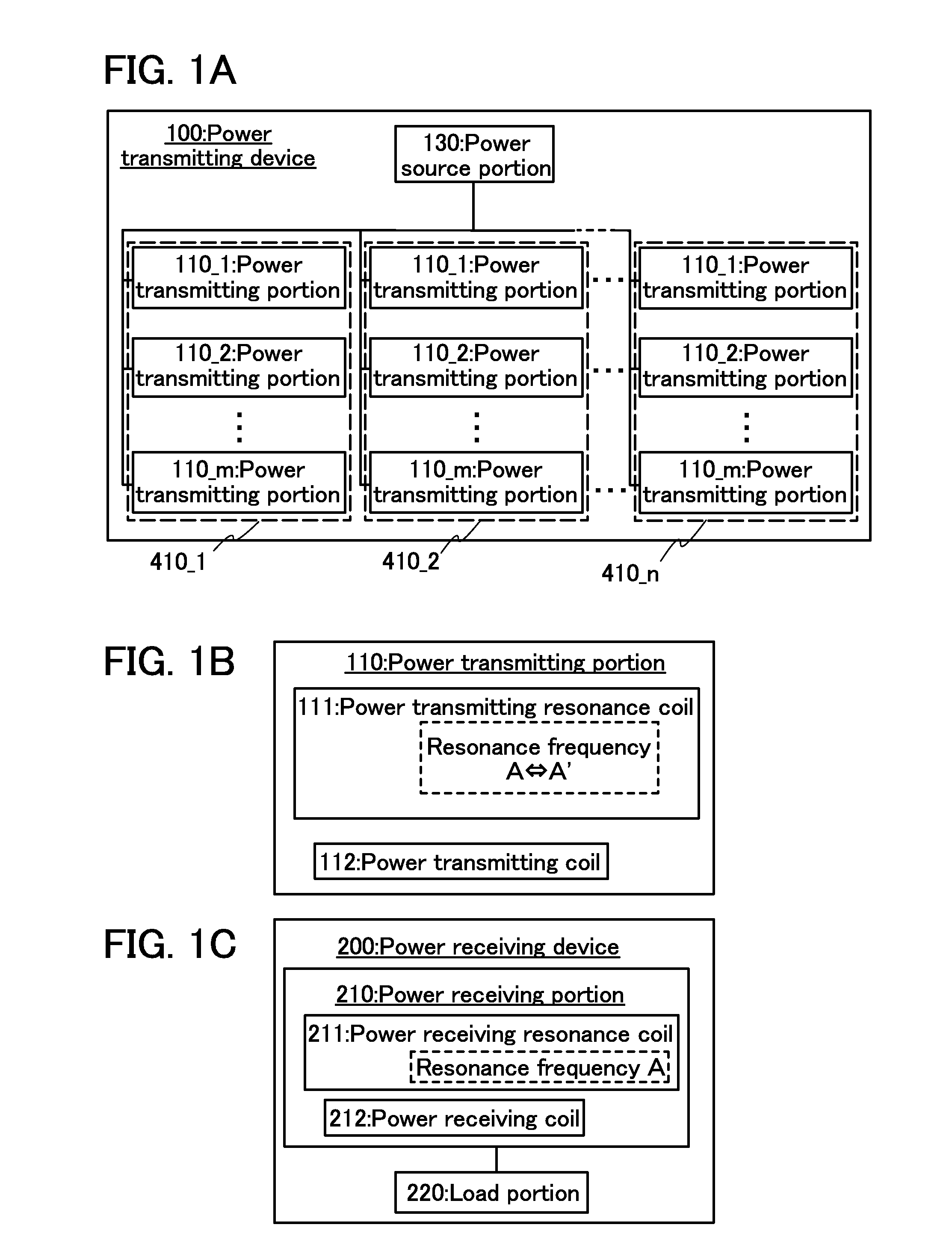
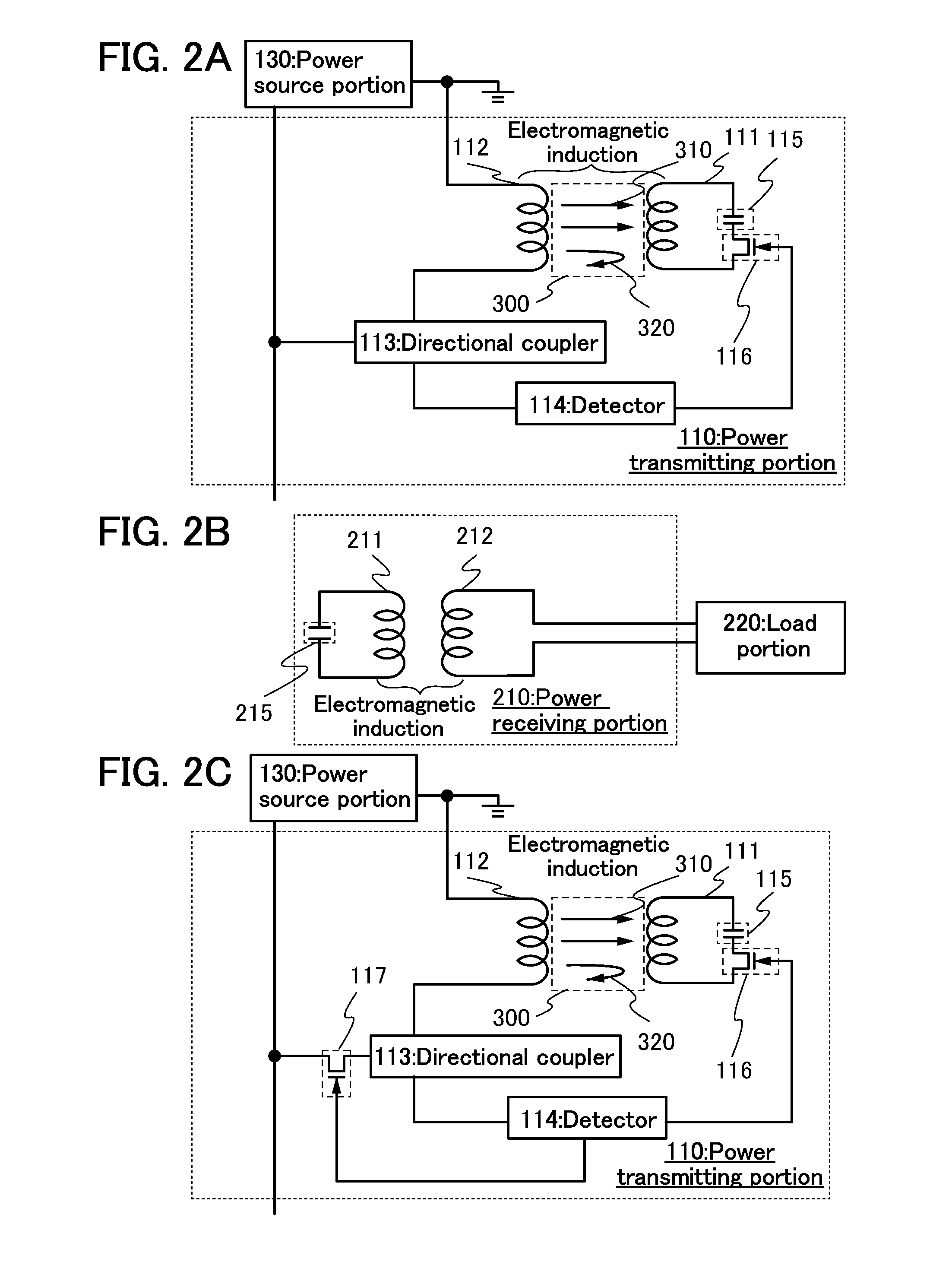
[0041]FIGS. 1A and 1B are block diagrams illustrating a structure of a power transmitting device which is included in the power feeding system, and FIG. 1C is a block diagram illustrating a structure of a power receiving device which is included in the power feeding system. However, a component and a function are not necessarily in a one-to-one relation, and a power feeding system may operate by relating a plurality of components and a plurality of functions to each other.

[0042]In the power feeding system in this embodiment, power is supplied from the power transmitting device which is electrically connected to the power sourc...

embodiment 2

[0113]In this embodiment, one embodiment in a case where the power receiving device is incorporated in an electric propulsion vehicle such as an electric vehicle in the power feeding system and the power feeding method which are described in Embodiment 1 will be described with reference to FIGS. 6A and 6B.

[0114]Note that the power receiving device can be incorporated in portable electronic devices such as digital video cameras, portable information terminals (e.g., mobile computers, mobile phones, portable game consoles, and e-book readers), and image reproducing devices including a recording medium (specifically digital versatile disc (DVD) reproducing devices) in addition to an electric propulsion vehicle such as an electric vehicle. Power can be fed to the electronic devices, in each of which the power receiving device is incorporated, in such a manner that the electronic devices are held and placed in a region capable of power feeding by users.

[0115]The power feeding system and ...


PUM


Abstract

To provide a power feeding system and the like with which charging can be performed without a decrease in the power supply efficiency. To provide a power feeding system and the like with which can offer a power feeding service which is efficient to both a power feeding user and a power feeding provider. The power transmission state in each of power transmitting portions is monitored, the power transmitting portion having the highest power transmission efficiency is selected based on positional advantage, and the power transmitting resonance coil included in the selected power transmitting portion is kept at a first resonance frequency, whereby power transmission continues. The resonance frequency of the power transmitting resonance coil included in the non-selected power transmitting portion (the number of the non-selected power transmitting portions may be plural) is set to a second resonance frequency, whereby power transmission is stopped.

Description

BACKGROUND OF THE INVENTION[0001]1. Field of the Invention[0002]The present invention relates to a power feeding system and a power feeding method.[0003]2. Description of the Related Art[0004]In recent years, electronic devices using power as a prime mover, as typified by mobile devices such as mobile phones or notebook personal computers, are often used while being carried. Also, transportation means such as bicycles and automobiles using electric power as a prime mover have been developed from the point of view of environmental cleanness and safety.[0005]Since such portable electronic devices and such transportation means are often used outdoors, it is difficult to constantly supply power from a commercial power supply distributed to each house, through wires. Therefore, the portable electronic devices and the transportation means are provided with batteries which are charged from a commercial power supply in advance and operate by power supply from the batteries.[0006]However, si...

Claims


Application Information

Patent Timeline
Patent Type & Authority Applications(United States)
IPC IPC(8): H04B5/00H02J7/00B60L5/00B60M7/00
CPCH04B5/0037H04B5/0087Y02D30/70
Inventor MIWA, MISAKOKAMATA, KOICHIROSHIONOIRI, YUTAKAMAEDA, SHUHEI
Owner SEMICON ENERGY LAB CO LTD
Why Eureka
Try Eureka