
Dielectric elastomer self-sensing using plane approximation

a dielectric elastomer and self-sensing technology, applied in the direction of piezoelectric/electrostrictive device details, instruments, device details, etc., can solve the problems of unnecessarily inhibiting the motion of dea/deg, increasing the cost and mass of the device, and limited information regarding the electromechanical state of the de itsel

Active Publication Date: 2013-10-31
AUCKLAND UNISERVICES LTD
View PDF7 Cites 21 Cited by
  • Summary
  • Abstract
  • Description
  • Claims
  • Application Information

AI Technical Summary

Benefits of technology

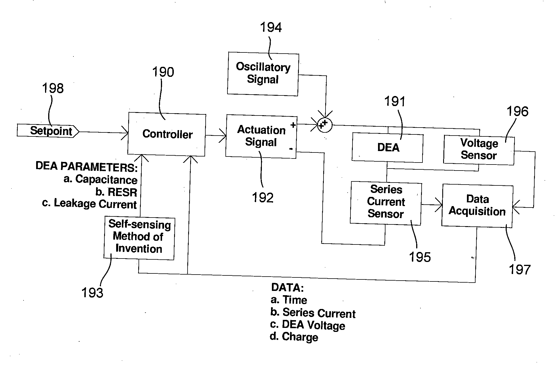
The invention is about a method and apparatus for estimating the state of a dielectric elastomer (DE) actuator or generator self-sensing or dielectric elastomer sensors. The method involves introducing a small-scale oscillation to the voltage difference between electrodes of the DE and measuring the potential difference across the DE and the series current through the DE over time. The feedback parameters derived from this data include the capacitance of the DE, leakage current through the DE, and the equivalent series resistance of the DE. The method can be used to estimate the state of the DE actuator or generator, and can also be used to control the actuation of the DEA.

Problems solved by technology

For DEA and DEG, coupling them directly to discrete rigid strain, displacement, velocity or acceleration sensors inevitably increases the cost and mass of the device, and while such a strategy is effective for traditional, rigid devices that are part of kinematically constrained structures, it unnecessarily inhibits the motion of DEA / DEG.
Similarly, attaching a sensor to a rigid body to which the DE is connected may provide useful feedback regarding the mechanical output, but provides limited information regarding the electromechanical state of the DE itself.
However, this and other self-sensing methods of the prior art typically have one or more disadvantages.
Alternatively, or additionally, the methods and / or apparatus of the prior art obtain estimates based upon other assumptions which may not always hold true, are not suitable for practical implementation in a system designed for portable use, are sensitive to noise, and / or require unnecessarily complex, numerous, or processor-intensive calculations to be performed.

Method used


Image

  • Dielectric elastomer self-sensing using plane approximation
  • Dielectric elastomer self-sensing using plane approximation
  • Dielectric elastomer self-sensing using plane approximation

Examples


second example embodiment

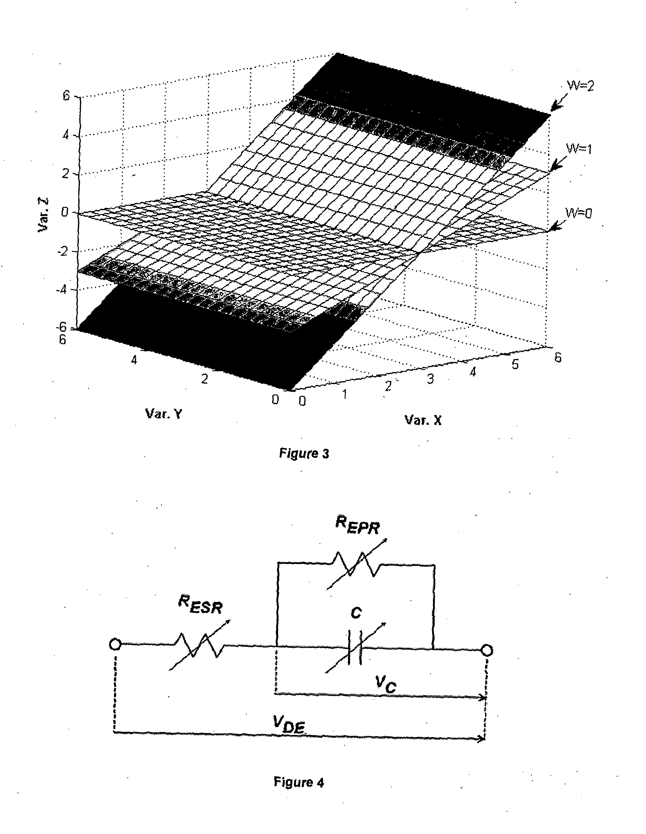
[0131]According to a second embodiment described below by way of a further example of the method of the present invention, the method involves deriving data regarding three variables comprising two electrical characteristics of a dielectric elastomer (DE), and time. These three variables are defined as orthogonal x-, y- and z-axes forming a three-dimensional space, and a plane of best fit through the data therefore comprises a plane.

[0132]This second example of the invention will be described below with respect to application of the method in relation to a dielectric elastomer actuator (DEA) system. However, the method may be similarly applied for a dielectric elastomer generator or sensor.

[0133]The DEA system uses Pulse Width Modulation (PWM) control of the input current (the actuation signal) to simultaneously actuate the DEA and introduce a small-scale oscillation to the voltage difference between the DE electrodes. This enables the capacitance of the DEA, leakage current through...


PUM


Abstract

The present invention provides a method for obtaining feedback parameters related to the state of a dielectric elastomer (DE). The method comprises introducing a small-scale oscillation to the voltage difference between electrodes of the DE, monitoring or repeatedly measuring several measurable electrical characteristics of the DE, deriving other relevant data from the measurements, deriving an equation for a plane of best fit through the relevant data when defined as orthogonal axes, and deriving the feedback parameters from coefficients of the plane equation. The method thus provides important feedback regarding the capacitance, leakage current and / or electrode resistance of the DE. Also disclosed are a computer program and a system adapted to perform the method.

Description

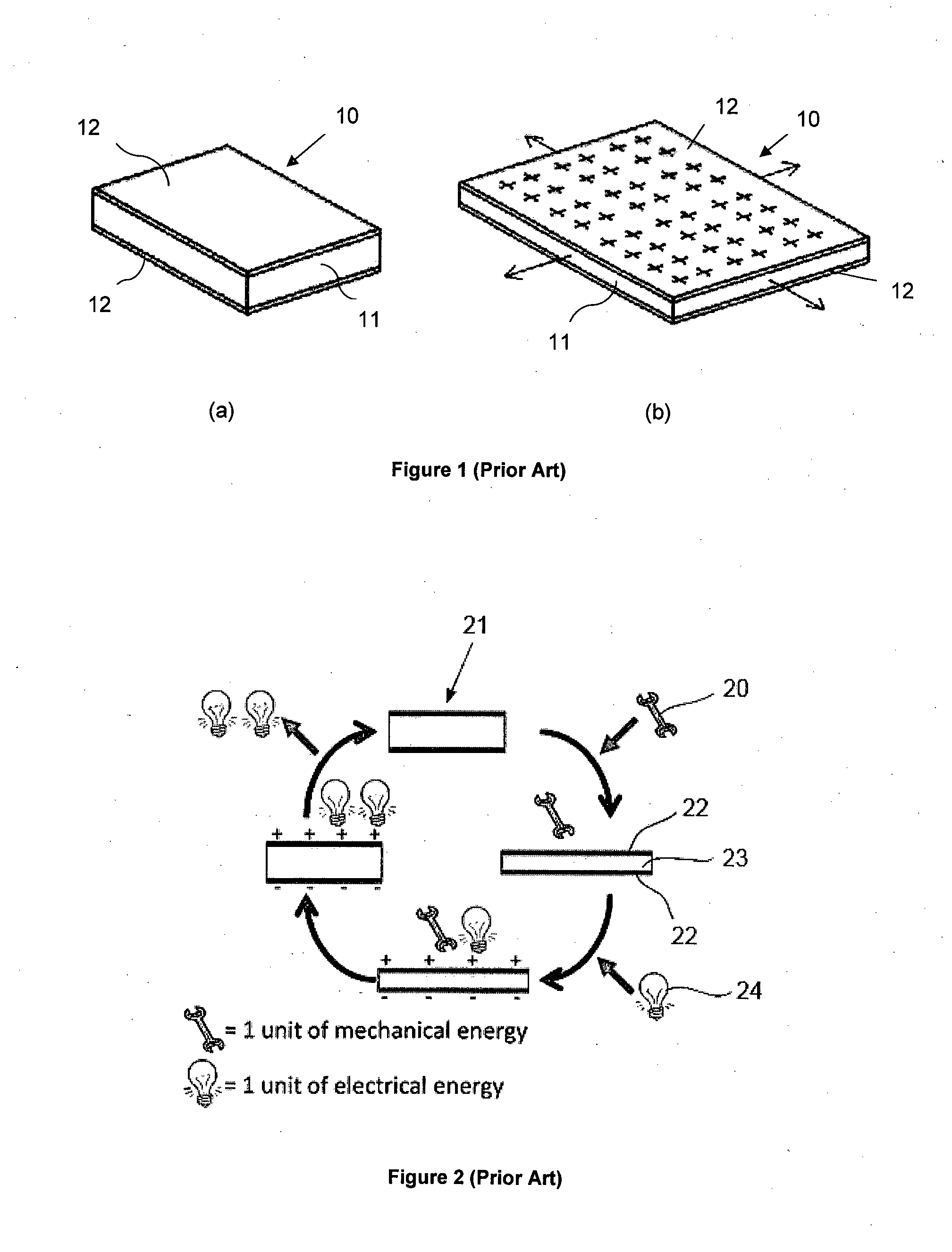
FIELD[0001]This invention relates to a method and apparatus for sensing electrical parameters of a dielectric elastomer (DE). More particularly, the invention relates to self-sensing by dynamically estimating the electrical parameters of the DE and deriving an estimate of the state of the DE from those parameters.BACKGROUND[0002]A dielectric elastomer (DE) can be used to convert electrical energy into mechanical energy, or vice versa. DEs can be used as actuators, generators, and / or sensors.[0003]Referring to FIGS. 1(a) and 1(b), a DE (generally referenced 10) typically comprises a volumetrically incompressible dielectric elastomer membrane 11 provided between compliant electrodes 12.[0004]Dielectric Elastomer Actuators (DEA) deform when a voltage difference is applied across the electrodes 12, as disclosed in “Electrostriction of polymer dielectrics with compliant electrodes as a means of actuation” (Pelrine R. E., Kornbluh R. D., & Joseph J. P., Sensors and Actuators, A: Physical ...

Claims


Application Information

Patent Timeline
Patent Type & Authority Applications(United States)
IPC IPC(8): G01R27/26H10N30/20H10N30/80H10N30/098
CPCG01R27/2617H02N2/062H10N30/802H10N30/20H10N30/098
Inventor O'BRIEN, BENJAMIN MARCGISBY, TODD ALANANDERSON, IAIN ALEXANDER
Owner AUCKLAND UNISERVICES LTD
Learn More