
Hot-water heater manufacturing method and hot-water heater manufactured by the same

Inactive Publication Date: 2013-10-31
MITSUBISHI HEAVY INDUSTIRES AUTOMOTIVE THERMAL SYST CO LTD
View PDF16 Cites 11 Cited by
  • Summary
  • Abstract
  • Description
  • Claims
  • Application Information

AI Technical Summary

Benefits of technology

The present invention describes a hot-water heater manufacturing method and hot-water heater that have stable heat exchange characteristics and improved reliability. The method uses a simple and easy process to apply a moderate contact surface pressure between the heating-medium circulating tubes and the heater members while enhancing the joint strength between the heating-medium circulating tubes.

Problems solved by technology

On the other hand, in hybrid vehicles that run on power from an engine in combination with power from an electric motor and in electric vehicles that run on only driving force of an electric motor, such as electric cars, because the engine is stopped during driving or an engine is not installed therein, it is impossible to perform effective vehicle heating by using the heat of engine cooling water.
Thus, for example, in hybrid vehicles, a hot-water heater for heating is connected to the engine cooling water path, and, when the heating capability is insufficient because it is hard to increase the temperature of the engine cooling water during fuel-efficient driving etc., the hot-water heater additionally heats the engine cooling water to complement heating performed by the heater core.

Method used


Image

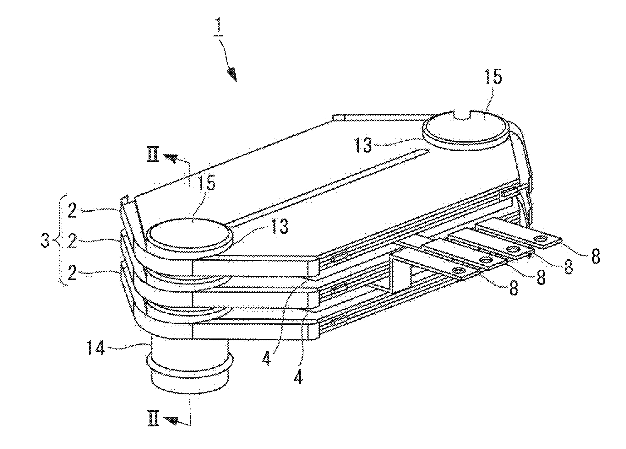
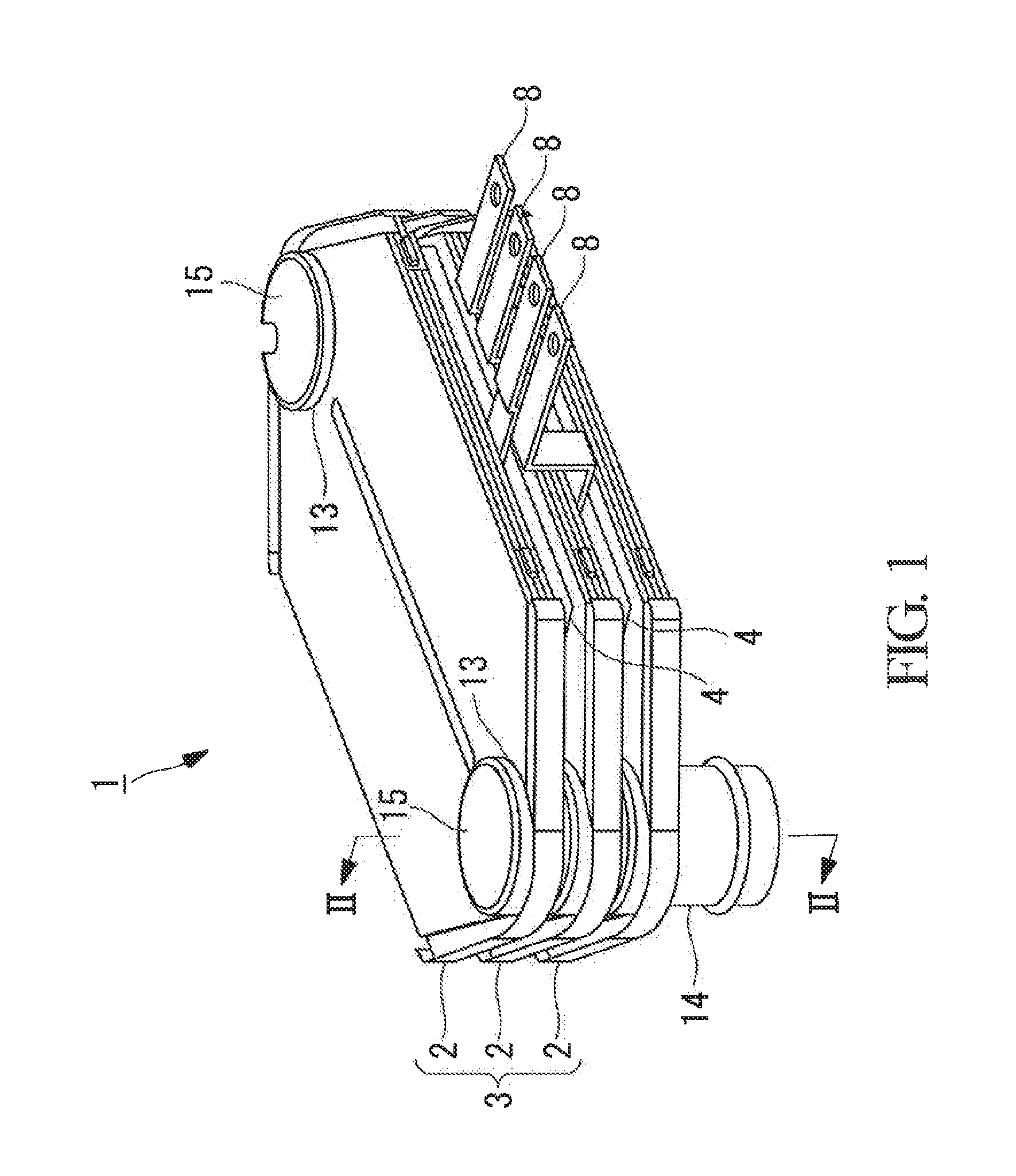
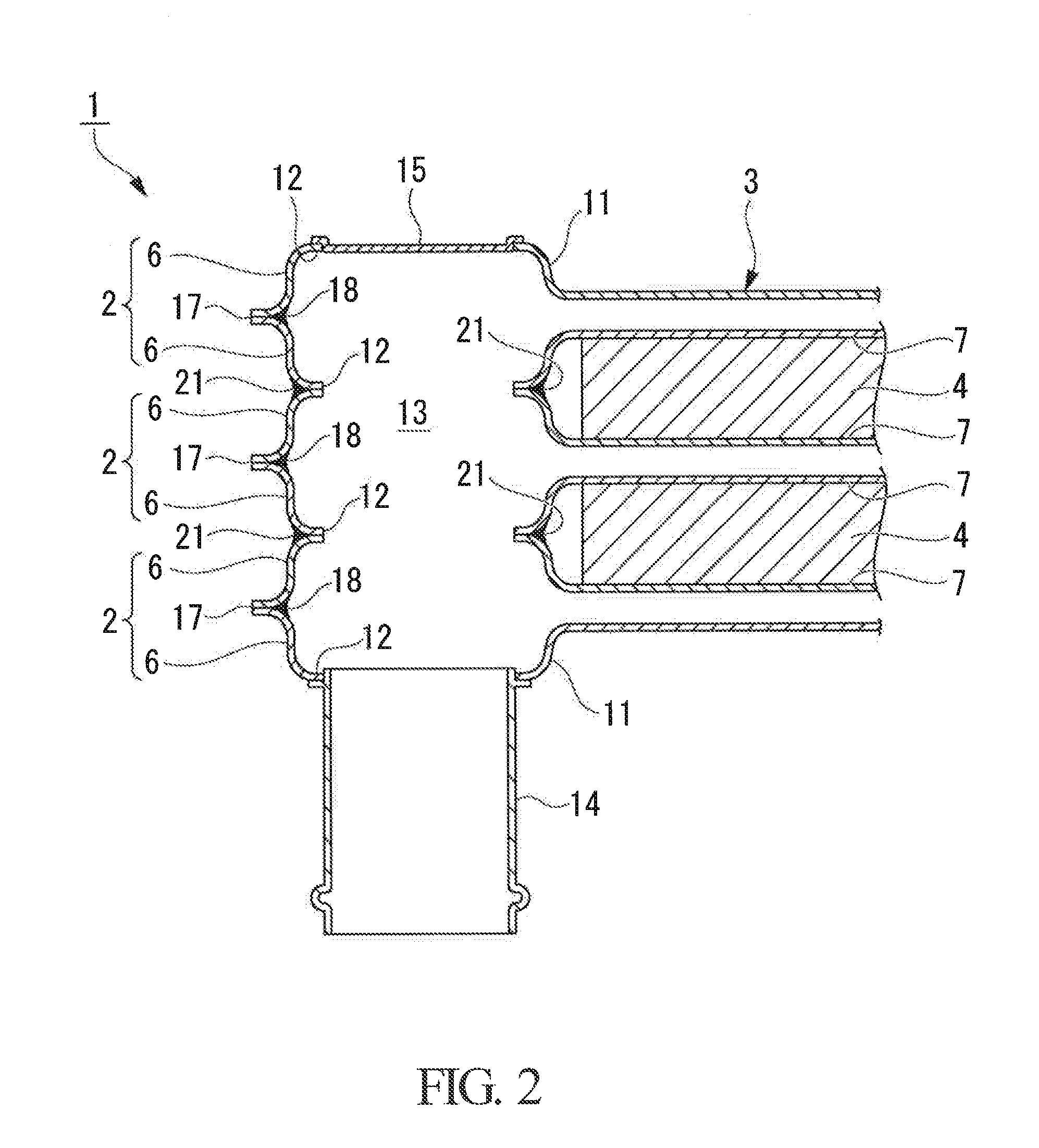
  • Hot-water heater manufacturing method and hot-water heater manufactured by the same
  • Hot-water heater manufacturing method and hot-water heater manufactured by the same
  • Hot-water heater manufacturing method and hot-water heater manufactured by the same

Examples


first embodiment

[0041]Next, a hot-water heater manufacturing method according to a first embodiment of the present invention will be described with reference to FIGS. 3 and 4. The hot-water heater manufacturing method includes a heating-medium circulating tube forming step A, a positioning and pressing step B, and a tube joining step C.

A. Heating-Medium Circulating Tube Forming Step

[0042]FIGS. 3(a) to 3(c) show the heating-medium circulating tube forming step A of forming the heating-medium circulating tubes 2. As shown in FIG. 3(a), each of the heating-medium circulating tubes 2 is composed of a pair of upper-and-lower tube constituent members 6. The tube constituent members 6 are made of a sheet-metal material, such as aluminum or brass, as described earlier, and are pressed into shapes, the tank convex portions 11 are formed in the shape of bulges at both ends thereof, and joining margins 17 are formed around the entire circumferences thereof.

[0043]The tube constituent members 6, forming a pair,...

second embodiment

[0056]Next, a hot-water heater manufacturing method according to a second embodiment of the present invention will be described with reference to FIGS. 5(a) to 5(d). The hot-water heater manufacturing method includes the heating-medium circulating tube forming step A, a positioning and pressing step B, and a tube joining step C.

A. Heating-Medium Circulating Tube Forming Step

[0057]Because the structure of the heating-medium circulating tube 2 and the heating-medium circulating tube forming step A of forming the heating-medium circulating tube 2 are the same as the heating-medium circulating tube forming step A of the first embodiment, shown in FIGS. 3(a) to 3(c), a description thereof will be omitted. However, after FIG. 3(c), a step of attaching, in advance, a brazing filler metal 24 to the circumferential portions of the heating-medium circulating holes 12 of the heating-medium circulating tubes 2, as shown in FIG. 5(a), is added. Thus, a state in which the brazing filler metal 24 ...

third embodiment

[0062]Next, a hot-water heater manufacturing method according to a third embodiment of the present invention will be described with reference to FIGS. 6(a) to 6(d). The hot-water heater manufacturing method includes the heating-medium circulating tube forming step A, a positioning and pressing step B, and a tube joining step C.

A. Heating-Medium Circulating Tube Forming Step

[0063]Because the structure of the heating-medium circulating tube 2 and the heating-medium circulating tube forming step A of forming the heating-medium circulating tube 2 are the same as the heating-medium circulating tube forming step A of the first embodiment, shown in FIGS. 3(a) to 3(c), a description thereof will be omitted. As shown in FIG. 6(a), on the circumference of one (for example, lower) side of the upper-and-lower heating-medium circulating holes 12 of each of the heating-medium circulating tubes 2 of the third embodiment, an upright fitting flange 27 (fitting part) that is formed continuously in th...


PUM

PropertyMeasurementUnit
Diameteraaaaaaaaaa
Shapeaaaaaaaaaa
Strengthaaaaaaaaaa

Abstract

Provided is a hot-water heater manufacturing method capable of obtaining stable heat exchange characteristics by applying a moderate contact surface pressure between heating-medium circulating tubes and heater members that constitute a hot-water heater, and capable of improving the reliability by enhancing the joint strength between the heating-medium circulating tubes, with a simple and easy manufacturing process.

Description

TECHNICAL FIELD[0001]The present invention relates to a hot-water heater manufacturing method in which heaters are installed between a plurality of flow channels in which a heating medium flows, thus heating the heating medium, and also relates to a hot-water heater manufactured by this method.BACKGROUND ART {0002}[0002]In general vehicles that run on power from an engine, as is well known, engine cooling water serving as a heating medium is circulated to a heater core, and air-conditioning air is made to pass through the heater core to perform heat exchange, thereby performing vehicle heating. On the other hand, in hybrid vehicles that run on power from an engine in combination with power from an electric motor and in electric vehicles that run on only driving force of an electric motor, such as electric cars, because the engine is stopped during driving or an engine is not installed therein, it is impossible to perform effective vehicle heating by using the heat of engine cooling ...

Claims


Application Information

Patent Timeline
IPC IPC(8): F24H1/10B21D51/24
CPCF24H1/105B21D51/24F28D9/0043F24H1/121F24H9/1827F24H2250/04F24H1/009F24H9/146F28F2275/04B23K1/0012Y10T29/49393Y10T29/49387Y10T29/49389F28D1/0333F28F2275/045
Inventor YOSHITOMI, KEISAITO, KATSUHIRO
Owner MITSUBISHI HEAVY INDUSTIRES AUTOMOTIVE THERMAL SYST CO LTD
Learn More