Fuel cell

a fuel cell and cell technology, applied in the field of fuel cells, can solve the problem that the catalyst layer cannot function sufficiently, and the problem remains unsolved, so as to reduce the resistance overvoltage and increase the cell voltage

Inactive Publication Date: 2013-10-31
NISSAN MOTOR CO LTD
View PDF3 Cites 4 Cited by
  • Summary
  • Abstract
  • Description
  • Claims
  • Application Information

AI Technical Summary

Benefits of technology

[0009]According to the present invention, since all of the gas for power generation passes through the porous ribs, the amount of gas for power generation passing through in the porous ribs may be increased with the oxygen gas diffusibility into the catalyst layer near the porous ribs improved, and cell voltage may be increased by reducing resistance overvoltage.

Problems solved by technology

However, in the conventional fuel cell that is described in the above mentioned Japanese Patent Publication, since the gas for power generation is likely to flow into the space between the projections than in the projections and the gas for power generation is less likely to pass into the projection, thus gas for power generation cannot diffuse into a catalyst layer near the projections so that the problem remains unsolved that the catalyst layer cannot function sufficiently.

Method used


Image

  • Fuel cell
  • Fuel cell
  • Fuel cell

Examples


Embodiment Construction

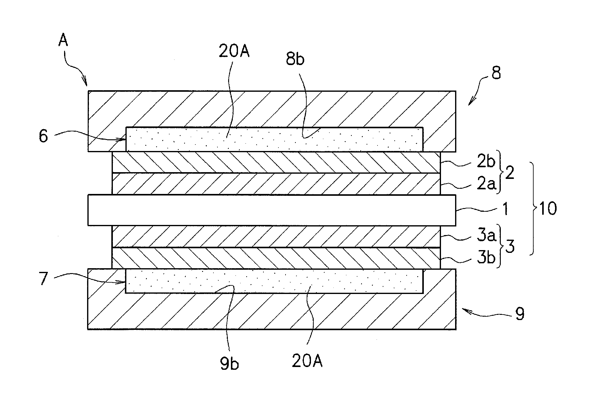
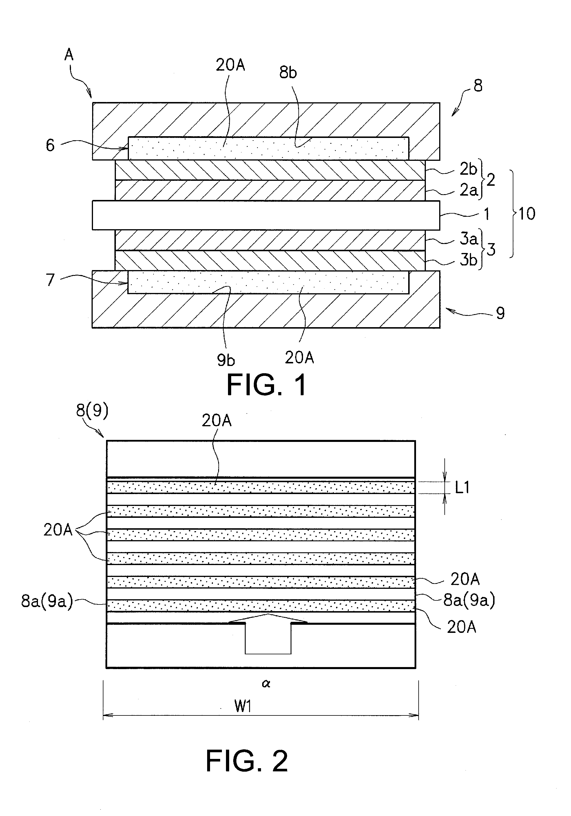
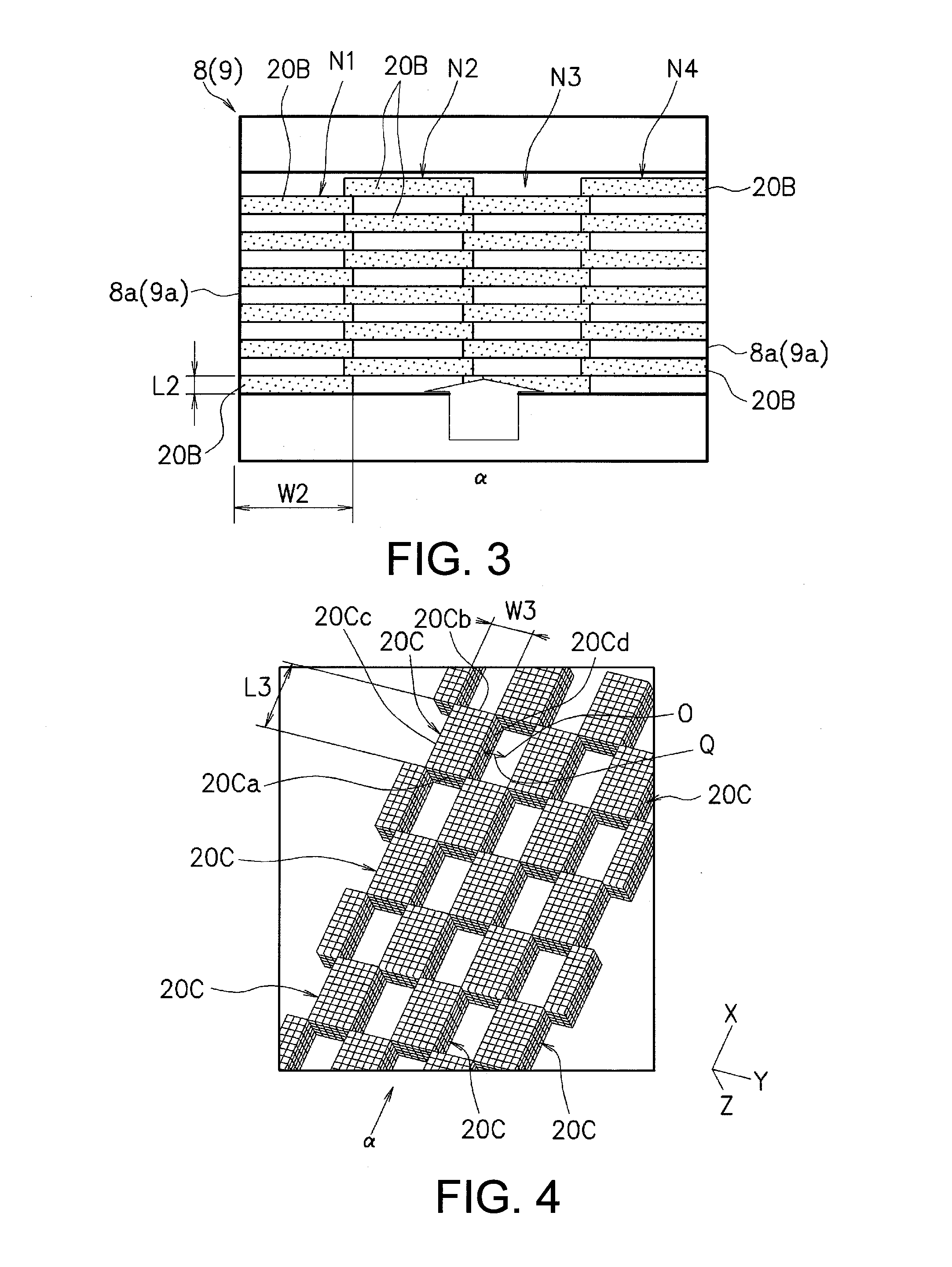
[0022]Configuration for carrying out the present invention is now described with reference to the drawings. FIG. 1 is a cross-sectional view of a fuel cell in one embodiment according to the present invention. FIG. 2 is a plan view of a separator of the above fuel cell forming an example of array pattern of porous ribs. FIG. 3 is a plan view of a separator forming an array pattern of porous ribs pertaining to a first modification.

[0023]As shown in FIG. 1, in the fuel cell A pertaining to the first embodiment according to the present invention, a pair of separators 8, 9 are disposed so that gas passages or channels 5, 7 for respectively circulating two types of gases for power generation on both surfaces of a cell assembly or structure 10.

[0024]The cell structure 10 is an integral structure formed with a cathode 2 and an anode 3 that are bonded on both sides of a solid polymer electrolyte1. The cathode 2 has a two-layer structure with a cathode catalyst layer 2a and an anode gas diff...


PUM

PropertyMeasurementUnit
porosityaaaaaaaaaa
particle diameteraaaaaaaaaa
width W3aaaaaaaaaa

Abstract

A fuel cell is provided that includes a cell structure, a pair of separators and a plurality of at least partially porous ribs. The cell structure includes an anode, a cathode and an electrolyte membrane, the anode and the cathode being laminated on opposite sides of the electrolyte membrane, respectively. The separators are disposed on both surfaces of the cell structure with gas passages being defined by the separators and the cell structure for circulating two types of gas for power generation. The porous ribs porous ribs are disposed successively on an entire cross-section of the gas passage in a transverse direction with a flow direction of the gas for power generation.

Description

[0001]This application is a U.S. National Stage of International Application No. PCT / JP2011 / 076521, filed Nov. 17, 2011. This application claims priority to Japanese Patent Application Nos. 2010-289600, filed on Dec. 15, 2010, and 2010-279808, filed on Dec. 27, 2010. The entire contents of these Japanese Patent applications are hereby incorporated herein by reference in their entirety.BACKGROUND[0002]1. Field of the Invention[0003]The present invention relates to a fuel cell having a plurality of at least partially porous ribs disposed in a gas passage for circulating two types of gases for power generation.[0004]2. Background Information[0005]As this type of fuel cell, one configuration is disclosed as described in Japanese Laid-Open Patent Application Publication No. 2010-129299. The fuel cell described in this Japanese Patent Publication is provided with a separator substrate or base member and formed with a gas passage in the surface of the separator base member for gas for powe...

Claims


Application Information

Patent Timeline
Patent Type & Authority Applications(United States)
IPC IPC(8): H01M8/10
CPCH01M8/1002H01M4/861H01M4/8626H01M8/0241H01M8/0247H01M8/0265H01M2004/8689H01M2008/1095H01M8/1007Y02E60/50H01M8/026
Inventor YOSHIZAWA, KOUDAI
Owner NISSAN MOTOR CO LTD
Why Eureka
Try Eureka