
Fuel cell system and method of controlling the same

a fuel cell and system technology, applied in the direction of fuel cell control, transportation hydrogen technology, electric generators, etc., can solve the problems of sharp reduction and inability to recover in time, and achieve the effect of effectively making cell voltage less likely or unlikely to be excessively reduced, easy detection of conditions, and easy detection of conditions

Active Publication Date: 2019-05-09
TOYOTA JIDOSHA KK
View PDF1 Cites 3 Cited by
  • Summary
  • Abstract
  • Description
  • Claims
  • Application Information

AI Technical Summary

Benefits of technology

The patent describes a fuel cell system that includes a fuel cell stack with multiple cells, gas supply units, and a controller that manages the gas supply. The controller uses a voltage detector to measure the voltage of the fuel cell stack and adjusts the gas supply to maintain the target voltage. The controller also detects crossleak, which is the gas leakage from one electrode to the other, and raises the target voltage to prevent the voltage drop. By adjusting the gas supply, the system ensures stable power generation and prevents the voltage drop caused by crossleak.

Problems solved by technology

In this case, even if the flow rate of cathode gas supplied is increased after detection of the crossleak, the cell voltage cannot be recovered in time, and may be reduced sharply to a voltage at which the cells deteriorate.

Method used


Image

  • Fuel cell system and method of controlling the same
  • Fuel cell system and method of controlling the same
  • Fuel cell system and method of controlling the same

Examples


first embodiment

A. First Embodiment

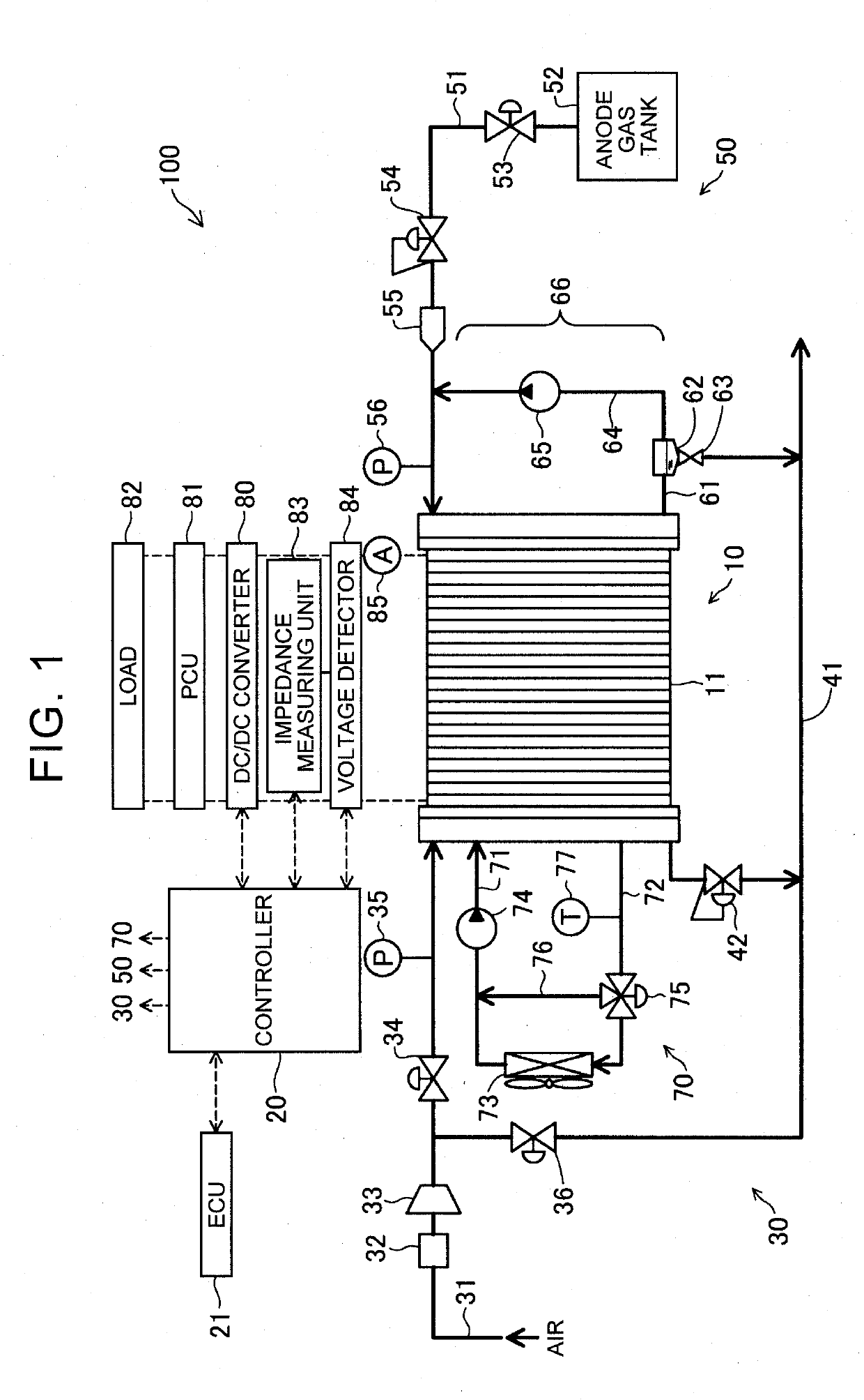
[0021]FIG. 1 schematically shows the configuration of a fuel cell system 100 according to one embodiment of the disclosure. The fuel cell system 100 includes a fuel cell stack 10, controller 20, cathode gas supply unit 30, anode gas supply unit 50, and cooling medium circulating unit 70. The fuel cell system 100 also includes a DC / DC converter 80, power control unit (which will be referred to as “PCU”) 81, load 82, impedance measuring unit 83, and voltage detector 84. The fuel cell system 100 of this embodiment is installed on a fuel cell vehicle, for example.

[0022]The fuel cell stack 10 is a polymer electrolyte fuel cell that is supplied with anode gas (e.g., hydrogen gas) and cathode gas (e.g., air) as reaction gases, to generate electric power. The fuel cell stack 10 is composed of a plurality of unit cells 11 stacked together. Each unit cell 11 has a membrane electrode assembly (not shown) in which an anode electrode (not shown) and a cathode electrode (not sh...

second embodiment

B. Second Embodiment

[0067]The flowchart of FIG. 5 illustrates one example of the procedure of cathode gas supply control according to a second embodiment. The configuration of a fuel cell system of the second embodiment is identical with that of the fuel cell system of the first embodiment, and will not be described herein. The cathode gas supply control of the second embodiment is different from that of the first embodiment in that a liquid water purge process is performed when liquid water is accumulated, but is identical with that of the first embodiment in the other steps. The liquid water purge process is a scavenging process for reducing water that remains in the fuel cell stack 10, and water deposited on pipes, valves, etc. of the fuel cell system 100, by controlling respective constituent parts of the fuel cell system 100.

[0068]In the above first embodiment, after determining that the average cell voltage Vfc is lower than the target voltage Vm in step S140, the controller 2...


PUM

PropertyMeasurementUnit
voltage Vmaaaaaaaaaa

Abstract

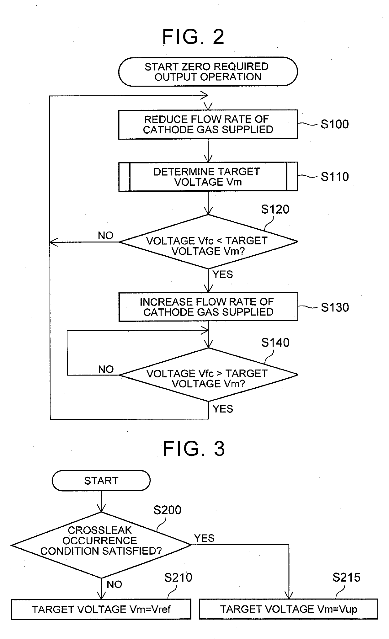
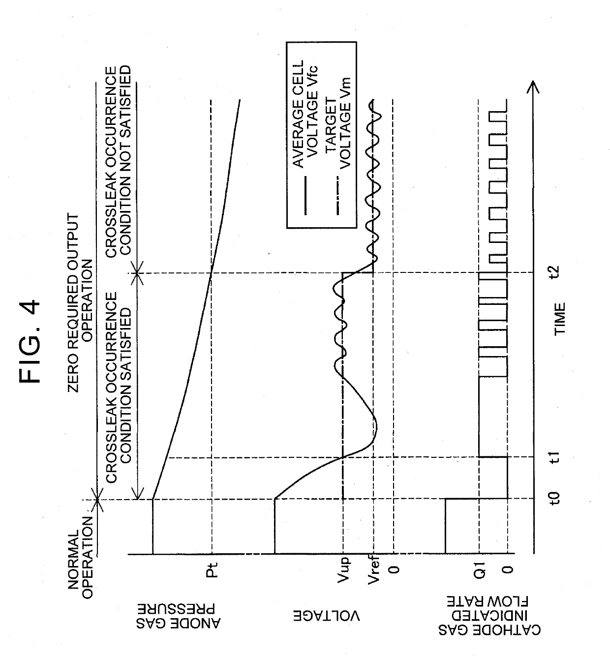
A controller of a fuel cell system performs cathode gas supply control to raise an average cell voltage of a fuel cell stack by increasing supply of cathode gas to the fuel cell stack, when electric power required to be generated by the fuel cell stack is equal to zero, and the average cell voltage is lower than a predetermined target voltage. Under the cathode gas supply control, the controller sets the target voltage when a predetermined condition indicating that crossleak is likely to occur is satisfied, to a value higher than a reference target voltage as the target voltage in the case where the condition is not satisfied.

Description

INCORPORATION BY REFERENCE[0001]The disclosure of Japanese Patent Application No. 2017-216004 filed on Nov. 9, 2017 including the specification, drawings and abstract is incorporated herein by reference in its entirety.BACKGROUND1. Technical Field[0002]The disclosure relates to a fuel cell system and a method of controlling the fuel cell system.2. Description of Related Art[0003]In a fuel cell system, when a gas passage is blocked with water produced (namely, when flooding occurs), a voltage value of each unit cell (which will be called “cell voltage”) is reduced, as known in the art. In a fuel cell system described in Japanese Unexamined Patent Application Publication No. 2012-227008 (JP 2012-227008 A), when the lowest cell voltage becomes lower than a predetermined value, the amount of cathode gas supplied to the cells is increased, so as to eliminate the flooding, and thus recover the cell voltage.SUMMARY[0004]In the meantime, when a fuel cell stack is not required to generate el...

Claims


Application Information

Patent Timeline
Patent Type & Authority Applications(United States)
IPC IPC(8): H01M8/04537H01M8/22H01M8/10H01M8/04746H01M8/0267
CPCH01M8/04559H01M8/222H01M8/10H01M8/04753H01M8/0267H01M2008/1095H01M8/04H01M8/04089H01M8/0488H01M8/04388H01M8/04619H01M2250/20H01M8/043Y02T90/40Y02E60/50H01M8/04783H01M8/04303H01M8/04328
Inventor NAMBA, RYOICHIISHIKAWA, TOMOTAKAFUJIMURA, YOSHIKATSU
Owner TOYOTA JIDOSHA KK
Learn More