Liquid-cooled internal combustion engine with a partially integrated exhaust manifold

a technology of internal combustion engine and exhaust manifold, which is applied in the direction of engine cooling, liquid cooling, cylinders, etc., can solve the problems of difficult to package the engine system, difficult to achieve the structure of the cylinder head, and different spacings, so as to reduce the travel length of hot exhaust gasses, minimize the thermal inertia of the partial piece, and the effect of little tim

Active Publication Date: 2013-11-07
FORD GLOBAL TECH LLC
View PDF9 Cites 14 Cited by
  • Summary
  • Abstract
  • Description
  • Claims
  • Application Information

AI Technical Summary

Benefits of technology

[0007]The present description of the approach to achieve the merging of the exhaust pipes at least partly within the cylinder head may offer several advantages. For example, integration of the part exhaust pipes in the cylinder head leads to a more compact construction of the internal combustion engine and a denser packaging in the engine bay. As such, a weight reduction of the internal combustion engine may be realized that leads to cost benefits during engine production and installation. Furthermore, the integration can have an advantageous effect on the arrangement and operation of an exhaust gas post-treatment system provided downstream in the exhaust gas discharge system. For example, in some embodiments, a reduced travel length of the hot exhaust gasses to various exhaust gas post-treatment systems provides little time for the exhaust gasses to cool before treatment, which may enable an exhaust gas post-treatment system to reach its operating temperature or trigger temperature as quickly as possible, in particular after a cold start of the internal combustion engine. In this context, extensive integrat...

Problems solved by technology

Furthermore, even if the exhaust pipes were to merge respectively into a part exhaust pipe forming a part exhaust manifold, wherein the outlet openings lie vertically above each other in the vertical direction, or in the direction of a cylinder longitudinal axis, the offset relative to each other may result in different spacings from the mounting face, which presents difficulties with respect to packaging of the engine system.
Implementation of liquid cooling systems often entails a complex structure of the cylinder head construction.
Therefore, integration of the part exhaus...

Method used


Image

  • Liquid-cooled internal combustion engine with a partially integrated exhaust manifold
  • Liquid-cooled internal combustion engine with a partially integrated exhaust manifold
  • Liquid-cooled internal combustion engine with a partially integrated exhaust manifold

Examples


Embodiment Construction

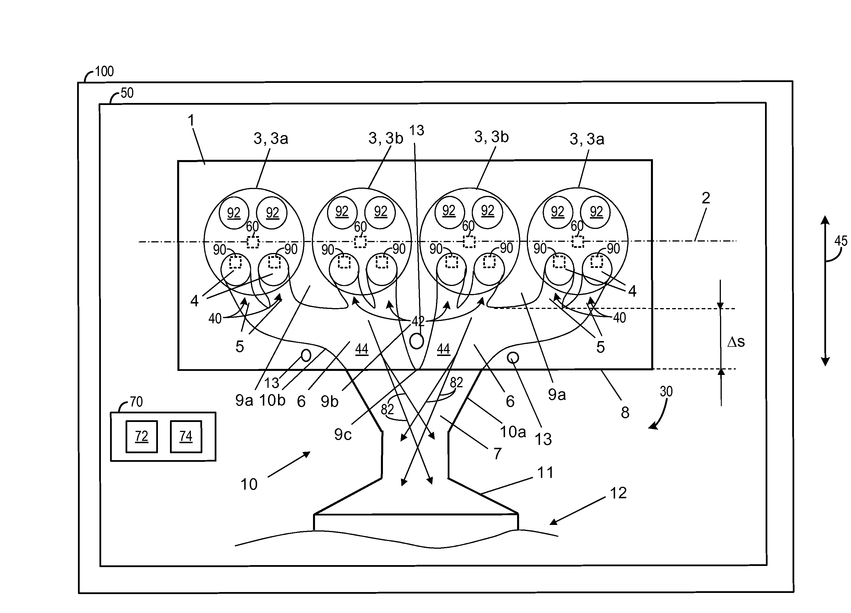
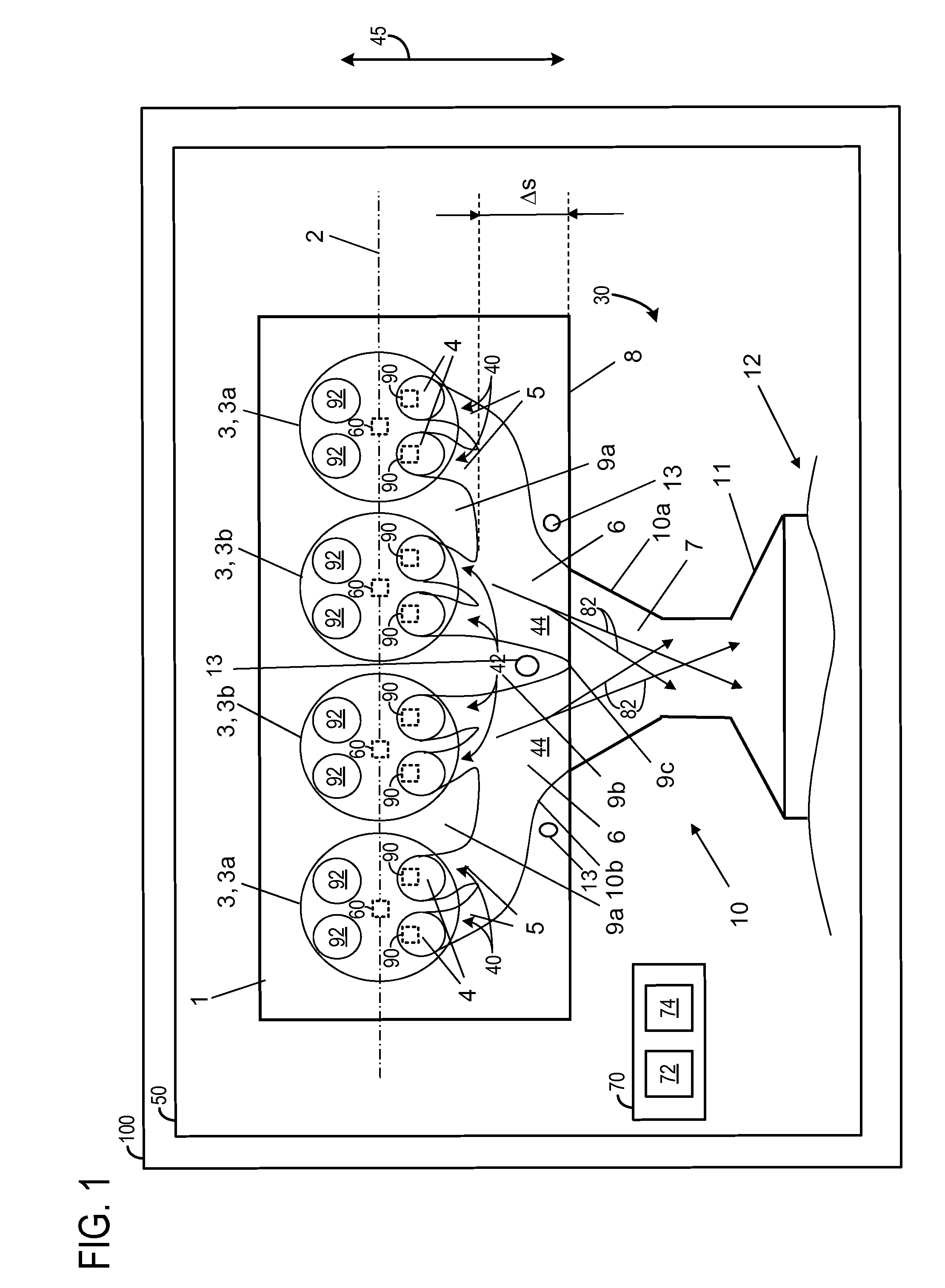
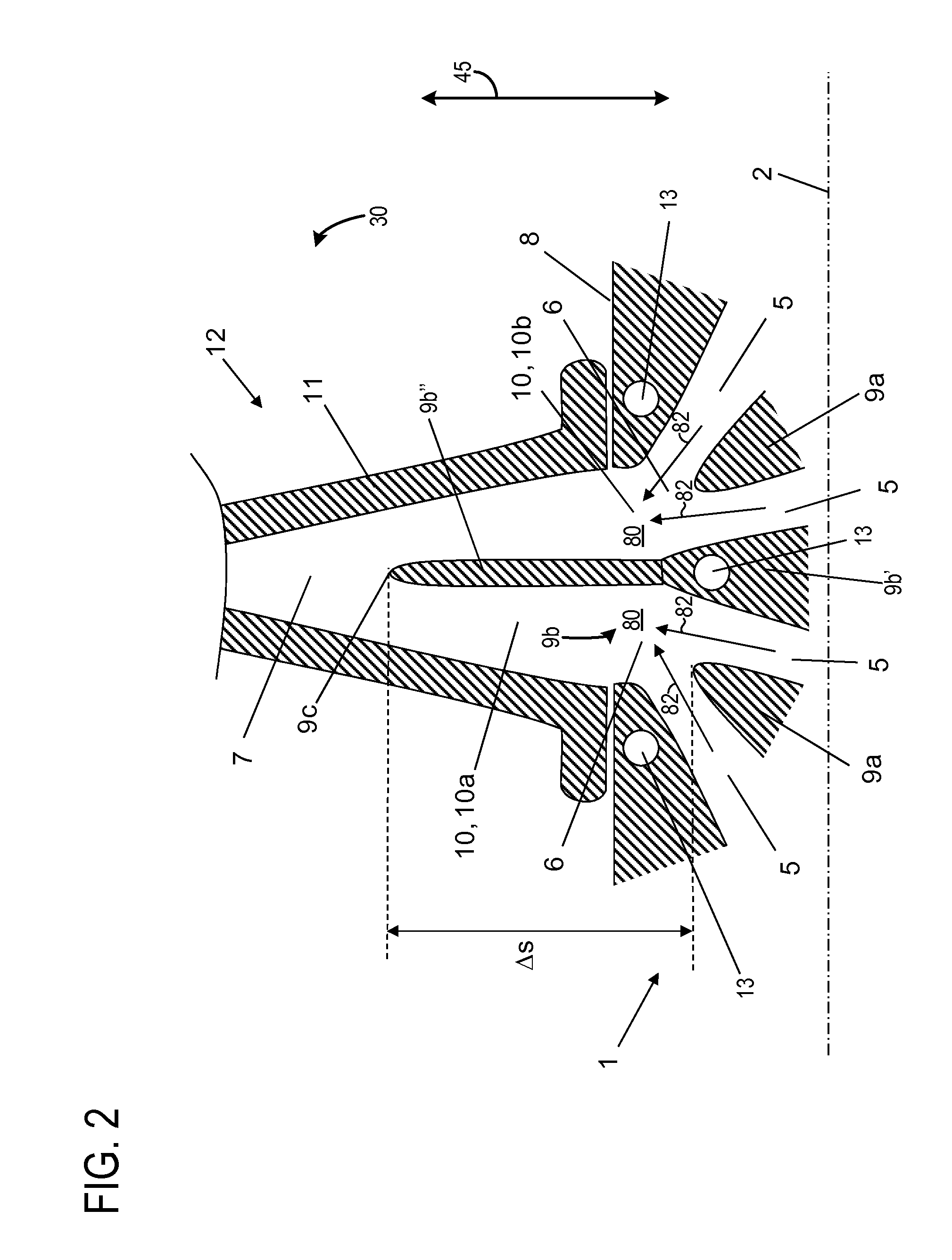
[0017]FIG. 1 shows schematically one embodiment of cylinder head 1 of an internal combustion engine 50 together with a segment of the inlet housing 11 of a turbine 12. Specifically, a cross-section of a cylinder head 1, a turbine 12, and an inlet 11 of the turbine 12 is illustrated in FIG. 1. Cylinder head 1 has four cylinders 3 which are arranged in line, for example, along the longitudinal axis 2 of cylinder head 1. Cylinder head 1 therefore has two outermost cylinders 3A and two innermost cylinders 3B. The engine 50 may be included in a vehicle 100. Although one cylinder head is depicted it will be appreciated that in other embodiments the engine 50 may include a second cylinder head having a similar configuration to cylinder head 1. Thus, the engine 50 may include a second bank of cylinders in some embodiments.

[0018]The cylinder head 1 may be further connected to a cylinder block to form combustion chambers. The cylinder block may include cylinder bores to accommodate pistons an...


PUM


Abstract

A liquid-cooled engine and method for its operation is described wherein the engine includes a cylinder head comprising at least one coolant jacket and exhaust manifold at least partially integrated therein. In one particular example, the exhaust pipes merge in stages within the cylinder head before merging into a common exhaust gas collector outside the cylinder head. Inclusion of a coolant system according to the present disclosure allows the thermal load of the cylinder head to be controlled, which thereby allows cooling to be achieved in a targeted manner inside the cylinder head by means of liquid cooling and forced convection.

Description

CROSS REFERENCE TO RELATED APPLICATIONS[0001]The present application claims priority to European Patent Application No. 12166516.0, filed on May 3, 2012, the entire contents of which are hereby incorporated by reference for all purposes.BACKGROUND AND SUMMARY[0002]Internal combustion engines have a cylinder block and at least one cylinder head connected together at their mounting faces to form the cylinder. The cylinders further have cylinder bores wherein pistons or cylinder linings reside. Within the cylinder bores, mobile pistons reciprocate axially along the guide to form the combustion chambers of the internal combustion engine.[0003]During the charge change, the combustion gasses are expelled via outlet openings of the cylinders and the combustion chambers are re-filled with fresh mixture or charge air via inlet openings. To control the charge change, an internal combustion engine includes control elements and activation devices designed to activate the control elements. For e...

Claims


Application Information

Patent Timeline
IPC IPC(8): F01P3/12
CPCF01P3/12F02F1/243F02F1/40
Inventor KUHLBACH, KAI SEBASTIAN
Owner FORD GLOBAL TECH LLC
Why Eureka
Try Eureka