
Methods and systems for a vehicle driveline power take off

Inactive Publication Date: 2013-11-07
FORD GLOBAL TECH LLC
View PDF1 Cites 27 Cited by
  • Summary
  • Abstract
  • Description
  • Claims
  • Application Information

AI Technical Summary

Benefits of technology

This patent describes a system that can provide power to a PTO output through a starter generator, allowing for both reversed PTO output and a smoother vehicle operation. By decoupling a new engine from the PTO, the system can also provide additional torque to the vehicle while operating the PTO. This improves the functionality of the PTO and enhances the vehicle's ability to operate safely and efficiently during PTO operation. The system may also improve communication with the operator during PTO operation.

Problems solved by technology

However, typical power take off ports are limited to rotating in a single direction.

Method used


Image

  • Methods and systems for a vehicle driveline power take off
  • Methods and systems for a vehicle driveline power take off
  • Methods and systems for a vehicle driveline power take off

Examples


Embodiment Construction

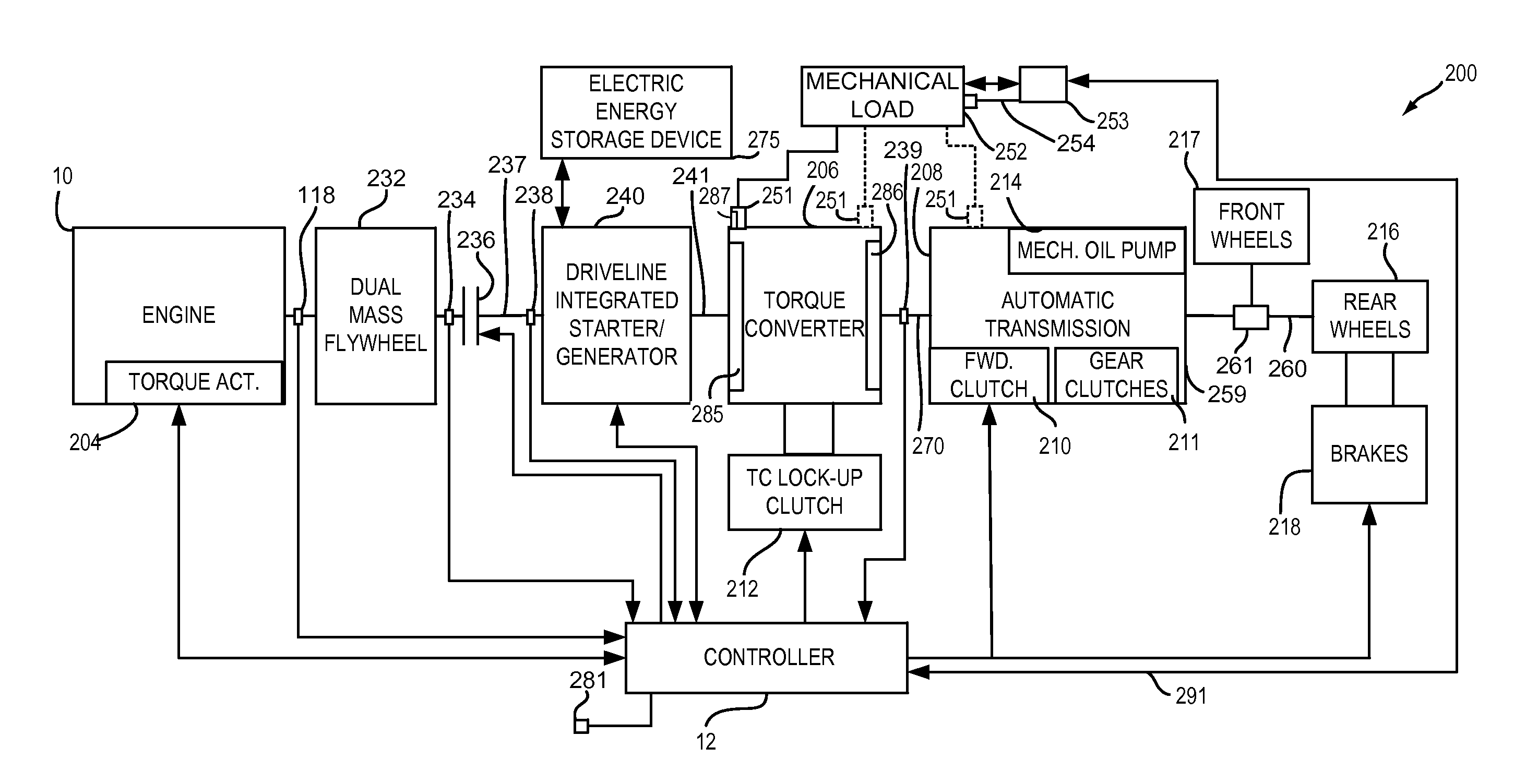
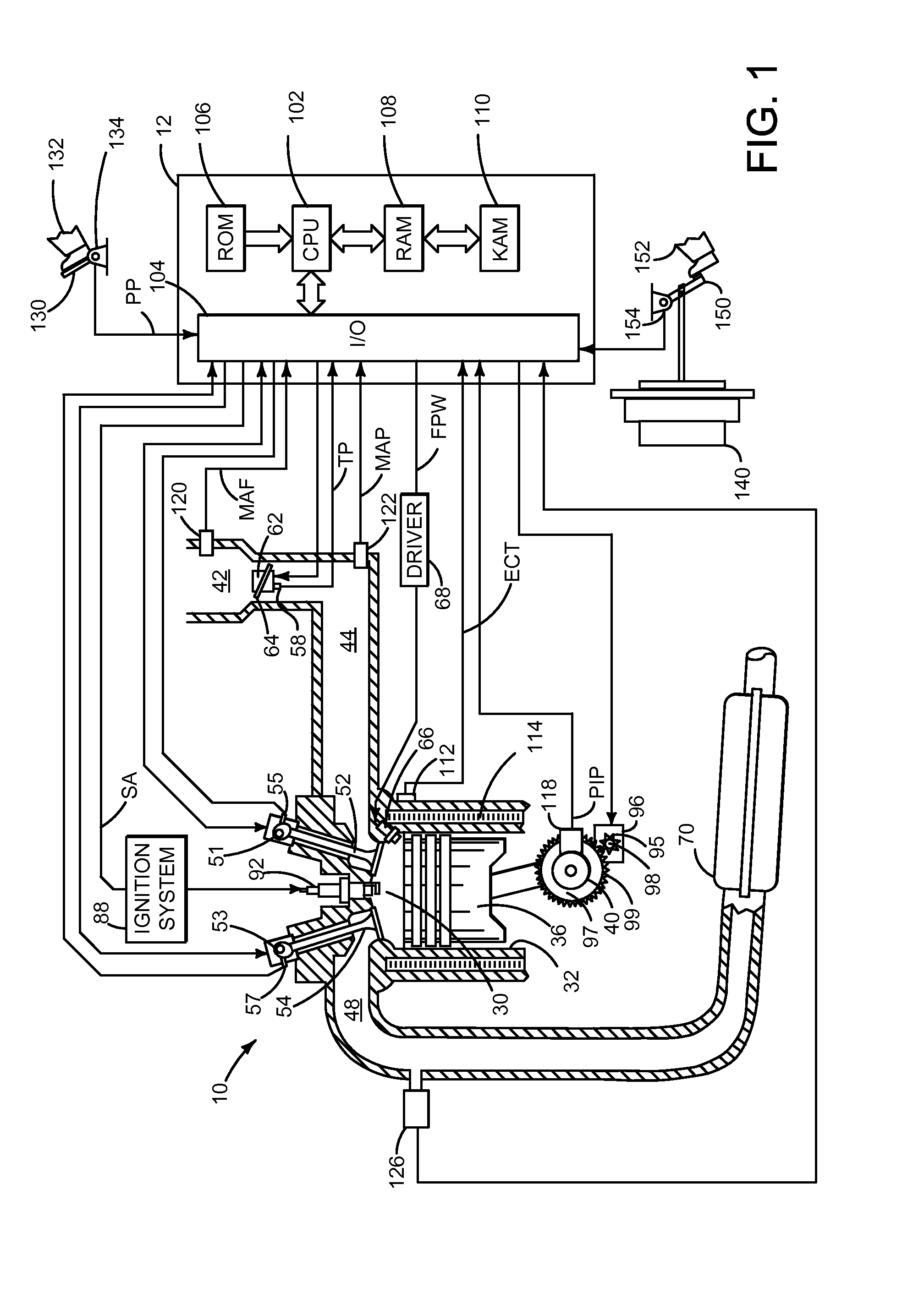
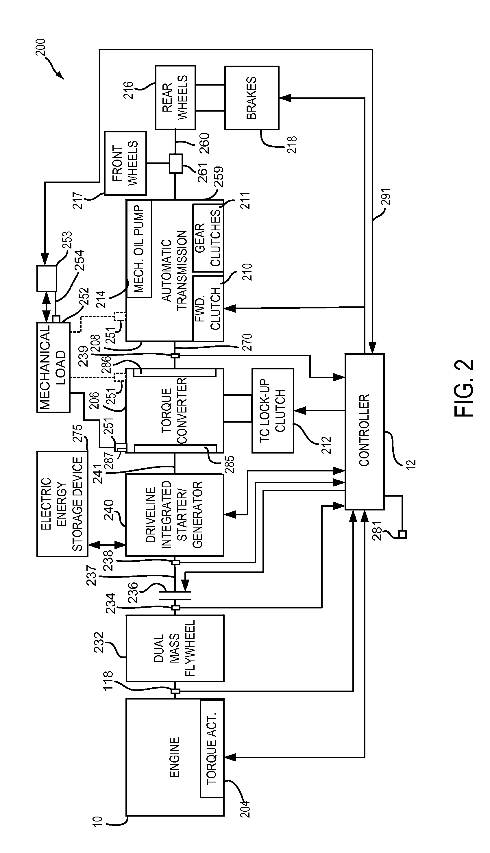
[0023]The present description is related to controlling a driveline of a hybrid vehicle. The hybrid vehicle may include an engine and electric machine as shown in FIGS. 1-3. The engine may be operated with or without a driveline integrated starter / generator (DISG) during vehicle operation. The driveline integrated starter / generator is integrated into the driveline on the same axis as the engine crankshaft and rotates whenever the torque converter impeller rotates. Further, the DISG may not be selectively engaged or disengaged with the driveline. Rather, the DISG is an integral part of the driveline. Further still, the DISG may be operated with or without operating the engine. The mass and inertia of the DISG remain with the driveline when the DISG is not operating to provide or absorb torque from the driveline. The vehicle driveline may be operated according to the method shown in FIGS. 4-10. FIGS. 11-13 show example vehicle operating sequences according to the method shown in FIGS....


PUM


Abstract

Systems and methods for improving operation of a power take off are presented. In one example, the power take off may be rotated in two different directions. The approaches may improve operation of a power take off device.

Description

CROSS REFERENCE TO RELATED APPLICATIONS[0001]The present application claims priority to United States of America Provisional Patent Application 61 / 643,156 filed on May 4, 2012, the entire contents of which are hereby incorporated by reference for all purposes.FIELD[0002]The present description relates to a system and methods for improving power take off operation of a vehicle. The methods may be particularly useful for engines that are selectively coupled to an electrical machine and a transmission.BACKGROUND AND SUMMARY[0003]Power from an engine is typically delivered to vehicle wheels to propel a vehicle. Additionally, engine power may be used to drive ancillary vehicle accessories such air conditioning and alternators. However, some vehicles include a power take off port located in the vehicle driveline between the engine and the wheels. The power take off can be a source of power to a device that is external to the vehicle or to a device that may not be incorporated into a typic...

Claims


Application Information

Patent Timeline
IPC IPC(8): B60K25/06
CPCB60K6/48B60W10/08B60W30/18045B60K2006/4825F02N11/003F02N11/04F02N11/0833F02N11/084F02N2200/124B60W10/26B60K6/52Y10S903/916Y10S477/90B60K17/28B60W10/30Y10S903/93B60W10/02B60W10/023B60W10/06Y02T10/40Y02T10/62B60W30/18018B60W20/40B60W30/18063B60W30/02B60W20/13B60W10/026B60W20/10B60W30/18B60W2510/1005B60W2520/403B60W2540/12B60W2540/16B60W2710/021B60W2710/024B60W2710/027B60W2710/065B60W2710/083B60Y2200/92B60Y2300/188B60Y2300/42B60Y2300/421B60Y2300/43B60Y2300/60F02D41/065F01P3/00
Inventor GIBSON, ALEX O'CONNORPIETRON, GREGORY MICHAELFUJII, YUJIDOERING, JEFFREY ALLENMCCALLUM, JAMES WILLIAM LOCH
Owner FORD GLOBAL TECH LLC
Features
  • Generate Ideas
  • Intellectual Property
  • Life Sciences
  • Materials
  • Tech Scout
  • Unparalleled Data Quality
  • Higher Quality Content
  • 60% Fewer Hallucinations
Learn More