
Method for producing optical film, optical film produced by the method, and polarizing plate and image-forming display device having the film

Inactive Publication Date: 2013-11-07
FUJIFILM CORP
View PDF3 Cites 82 Cited by
  • Summary
  • Abstract
  • Description
  • Claims
  • Application Information

AI Technical Summary

Benefits of technology

The present invention aims to address issues in the production of optical films by providing a method for producing an optical film that can be used at the front end of a display device. The production method can suppress repeling issues and does not cause interference unevenness, resulting in an excellent physical product.

Problems solved by technology

However, conventional retardation plates have such problems as that they are liable to form scratches and are insufficient in strength, that they show a high reflectance when irradiated with outer light, that they have poor light fastness, and that stains are liable to deposit thereon and are difficult to remove.
However, it has been found that, since the liquid crystalline compound layer generally has optical anisotropy, merely providing a protective film having no optical anisotropy on the liquid crystalline compound layer causes a problem that light interference conditions so greatly differ depending upon viewing angle that rainbow-like unevenness or the like tends to occur.
As a result, it has been found that, in comparison with common transparent supports, the support tends to repel a coating solution of the hard coat and tends to cause coating trouble.
As a result of analysis, projections of a matting agent used for forming projections for preventing adhesion of the transparent support roll film tend to cause adhesion.

Method used


Image

  • Method for producing optical film, optical film produced by the method, and polarizing plate and image-forming display device having the film
  • Method for producing optical film, optical film produced by the method, and polarizing plate and image-forming display device having the film
  • Method for producing optical film, optical film produced by the method, and polarizing plate and image-forming display device having the film

Examples


example

[0306]The characteristics of the invention will be more specifically described by reference to Working Examples and Comparative Examples. Materials, amounts of use, proportions, contents of treatments, treating manners, etc. can properly be altered as long as the gist of the invention is not exceeded. Therefore, the scope of the invention is not to be construed to be restricted by the specific examples to be described hereinafter.

[0307][Production Example 1 of Optical Film]

[Production 1 of Optical Substrate]

[0308]The following composition was placed in a mixing tank, and was stirred under heating to solve respective components, thus a cellulose acetate solution being prepared.

(Formulation of Cellulose Acetate Solution)

[0309]

Cellulose acetate of 60.7 to 61.1% in degree of100parts by weightacetificationTriphenyl phosphate (plasticizer)7.8parts by weightBiphenyldiphenyl phosphate (plasticizer)3.9parts by weightMethylene chloride (first solvent)336parts by weightMethanol (second solvent...


PUM

PropertyMeasurementUnit
Percent by massaaaaaaaaaa
Thicknessaaaaaaaaaa

Abstract

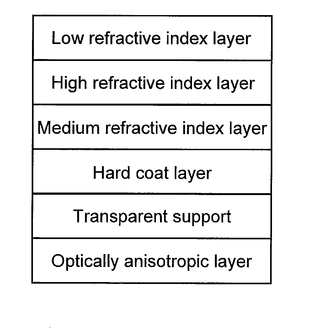
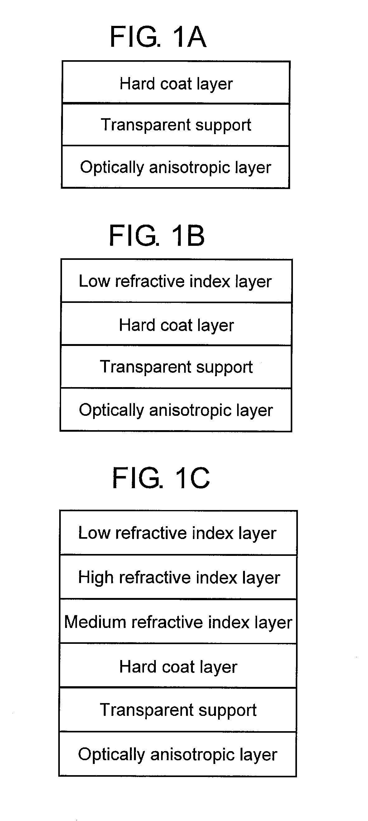
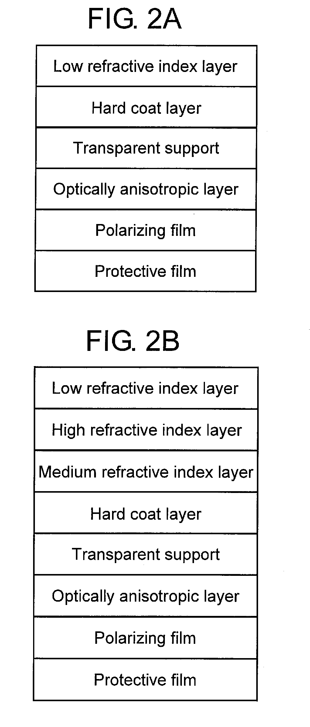
A method for producing an optical film including: laminating a hard coat layer on one side of an optical substrate in roll form, the hard coat layer having a transparent support and an optical anisotropic layer. The transparent support is laminated on the optical anisotropic layer, the one side is a transparent support-side of the optical substrate, the hard coat layer is obtained by coating, drying and curing a composition for forming a hard coat layer containing a curable monomer, a photo-polymerization initiator, and a solvent. The solvent is a mixture of at least one solvent selected from (S-1) and (S-2) and at least one solvent selected from (S-3), or a mixture of at least one solvent selected from (S-1) and at least one solvent selected from (S-2): (S-1) solvents dissolving the transparent support; (S-2) solvents swelling the transparent support; and (S-3) solvents neither dissolving nor swelling the transparent support.

Description

CROSS-REFERENCE TO RELATED APPLICATIONS[0001]This application is a Continuation of International Application No. PCT / JP2011 / 073765 filed on Oct. 7, 2011, which was published under PCT Article 21(2) in Japanese, which is based upon and claims the benefit of priority from Japanese Patent Application No. 2010-229146 filed on Oct. 8, 2010, the contents both of which are incorporated herein by reference.TECHNICAL FIELD[0002]The present invention relates to a method for producing optical film having a cured liquid crystalline compound, an optical film produced by the method, and a polarizing plate and an image-forming display device having the film.BACKGROUND ART[0003]A so-called retardation film to which various functions are imparted by controlling retardation of the film has been used for various applications.[0004]For example, retardation films have been designed for the purpose of expanding a viewing angle depending upon mode of a different kind of liquid crystal cell in a liquid cry...

Claims


Application Information

Patent Timeline
IPC IPC(8): G02B5/30G02B1/10B32B7/02B32B27/16G02B1/11G02B1/14G02B1/16G02B1/18G02F1/1335
CPCG02B5/3016G02B1/105B32B7/12B32B23/08B32B23/20B32B27/306B32B2250/03B32B2250/24B32B2255/10B32B2255/26B32B2305/55B32B2307/412B32B2307/42B32B2307/516B32B2307/706B32B2457/202G02B5/30Y10T156/10G02B1/14G02B1/16G02B1/18
Inventor YONEYAMA, HIROYUKITAKAHASHI, YUTAASAHI, MIHOIBARAKI, JUNKO
Owner FUJIFILM CORP
Learn More