Composite Polarizer With Adjustable Polarization Angles

a polarizing angle and composite technology, applied in the field of composite polarizers, can solve the problems of complex and bulky, linear polarizing cubes cannot achieve a maximum signal to noise ratio (snr), and are less efficient than reflective polarizers

Active Publication Date: 2013-11-07
KLA TENCOR TECH CORP
View PDF4 Cites 7 Cited by
  • Summary
  • Abstract
  • Description
  • Claims
  • Application Information

AI Technical Summary

Benefits of technology

[0009]An adjustable, composite polarizer can include first and second plate polarizers and an adjusting apparatus. The adjusting apparatus can adjust a pitch angle and a roll angle for the first and second plate polarizers while maintaining a predetermined distance between those plate polarizers. In this configuration, the adjustable, composite polarizer can provide mirror symmetric polarization with respect to an incident plane while providing the flexibility of any polarization and maintaining a minimal gap between the two parallel, abutting edges of the two plate polarizers.
[0010]In one embodiment, the adjusting apparatus can include hinges attached to abutting edges of two plate polarizer frames, each of which secures one plate polarizer. The frames can be open at the sides where the parallel, abutting edges of two polarizer plates meet, and the hinges can be located on the sides of frames that are outside the collection aperture to minimize blockage of collection aperture. An assembly frame can include a plurality of hinge rods. One set of hinge rods can be attached to the assembly frame to provide pitch angle adjustment. Another hinge rod can be used with an arc track to provide roll angle adjustment, wherein turning this hinge rod either folds the plates apart or together (equally). One or more motors can be connected to the hinge rods to provide motorized adjustment of the pitch and roll angles. In one embodiment, one motor can be used to turn the set of hinge rods for pitch adjustment, while another motor can be used to turn the hinge rod for roll adjustment. The adjusting apparatus can be configured to communicate with a processor, which can compute the pitch angle and the roll angle based on a desired polarization angle. In one embodiment, the processor can interface with a look-up table, which can store a plurality of desired polarization angles and their corresponding pitch and roll angles.

Problems solved by technology

Absorptive polarizers are more compact since it can operates at a normal incident angle, but are much less efficient than reflective polarizers because of absorption loss.
Therefore, a linear polarizing cube cannot achieve a maximum signal to noise ratio (SNR).
Such a system is complex and bulky, and polarization angles can only be adjusted in a set of discrete steps but not continuously, which makes it difficult to optimize for maximum SNR.
One of the disadvantages of the conventional “pizza pie” polarizers is the low efficiency due to the use of absorptive polarizers.
Unfortunately, a need still exists for a polarizer that has adjustable polarization angles while remaining mirror symmetric with a plane, e.g. the incident plane of a wafer inspection system with oblique illumination.

Method used


Image

  • Composite Polarizer With Adjustable Polarization Angles
  • Composite Polarizer With Adjustable Polarization Angles
  • Composite Polarizer With Adjustable Polarization Angles

Examples


Embodiment Construction

[0030]Polarized light detection can significantly improve defect sensitivity for both pattern and bare (un-pattern) wafer inspection tools. For example, a state of the art polarization mask for bare wafer inspection has been demonstrated to shown signal to noise improvement of over 20×.

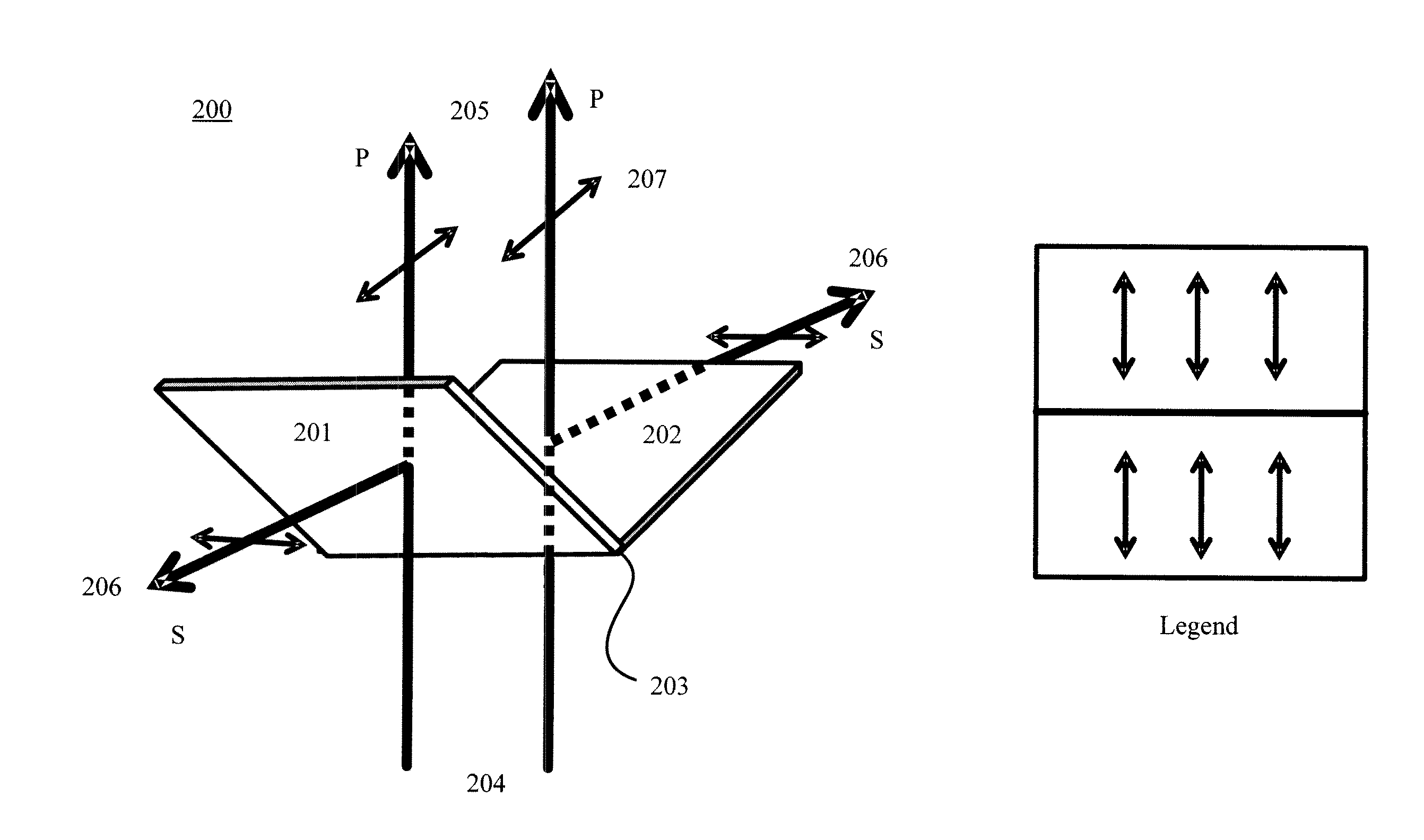
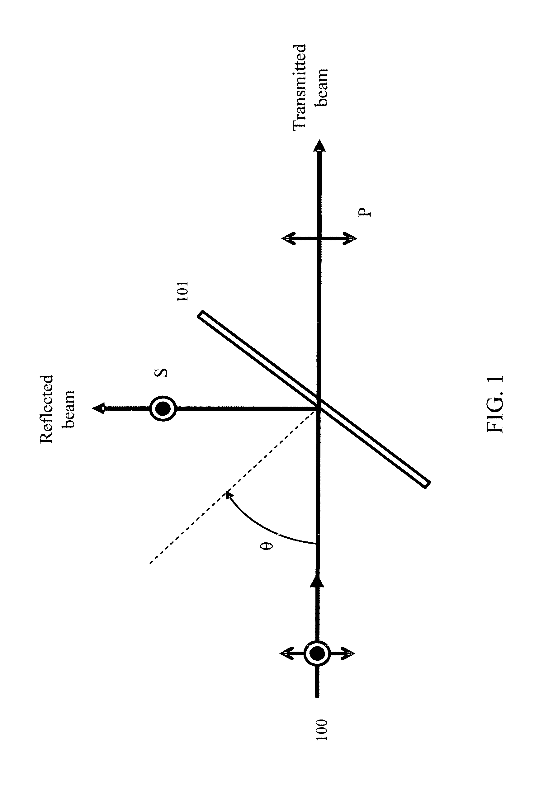
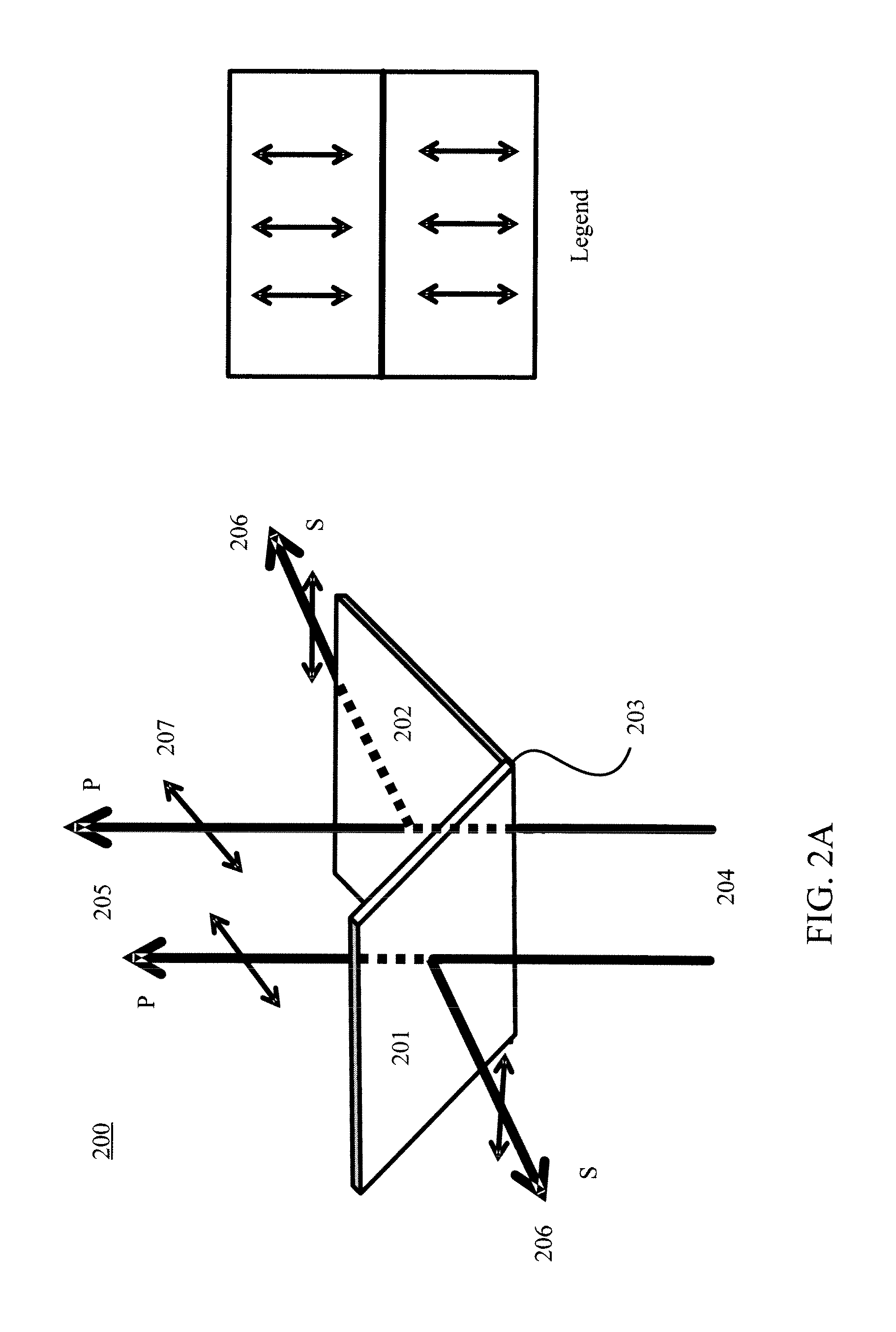
[0031]Referring to FIG. 1, a plane of incidence refers to a plane formed by a propagation direction of the incident light beam 100 and a surface normal of a thin film plate polarizer 101. The incident angle θ is angle between incoming light beam and surface normal of the plate polarizer 101. Typically, the polarization of the incident beam can be decomposed into two perpendicular components namely P and S, wherein P polarization is parallel to the plane of incidence and S polarization is perpendicular to that plane. S polarization component of the incident beam is reflected and P component is transmitted by the plate polarizer.

[0032]Generally, in a wafer inspection system using directional oblique ill...


PUM

PropertyMeasurementUnit
incident angleaaaaaaaaaa
pitch angleaaaaaaaaaa

Abstract

An adjustable, composite polarizer can include first and second plate polarizers and an adjusting apparatus. The adjusting apparatus can adjust a pitch angle and a roll angle for the first and second plate polarizers while maintaining a predetermined, minimal distance between those plates. In this configuration, the adjustable, composite polarizer can provide mirror symmetric polarization with respect to an incident plane while providing the flexibility of any polarization.

Description

RELATED APPLICATIONS[0001]This application claims priority of U.S. Provisional Patent Application 61 / 442,804, entitled “Mirror Symmetric Polarizer With Adjustable Polarization Angle” filed Feb. 15, 2011 and PCT Patent Application PCT / US12 / 25130, entitled “Composite Polarizer With Adjustable Polarization Angles” filed Feb. 14, 2012.BACKGROUND OF THE INVENTION[0002]1. Field of the Invention[0003]The present invention relates to a polarizer within an inspection system and in particular to a composite polarizer having a plurality of plate polarizers, each plate polarizer having a predetermined pitch angle and roll angle to provide a desired polarization.[0004]2. Related Art[0005]In general, using a polarizer in the imaging or collection path of a wafer inspection tool can take advantage of the distinctly different polarized scattered light from a wafer surface and from defects to significantly improve detection sensitivity. In a conventional wafer inspection tool, a linear polarizer wit...

Claims


Application Information

Patent Timeline
Patent Type & Authority Applications(United States)
IPC IPC(8): G02B27/28G01N21/21
CPCG02B5/3066G02B27/283G02B27/286G01N2021/8848G01N21/8806G01N21/9501G01N21/21
Inventor ZHAO, GUOHENG
Owner KLA TENCOR TECH CORP
Why Eureka
Try Eureka