Blade Sharpener

a blade and blade technology, applied in the field of blade sharpeners, can solve the problems of grinding dust from the blade clogging the pores of the abrasive wheel, the device has problems, and the blade is dulled, so as to prevent variations in the force of pressing the cutting edge and grind the blade further evenly and smoothly

Inactive Publication Date: 2013-11-07
HASEGAWA TOM HIROSHI +1
View PDF4 Cites 16 Cited by
  • Summary
  • Abstract
  • Description
  • Claims
  • Application Information

AI Technical Summary

Benefits of technology

[0009]Accordingly, the present invention is made with the above problems in mind, and it is an object of the present invention to provide a blade sharpener that is able to prevent variations in the force of pressing the cutting edge against conical surfaces of an abrasive wheel and can grind blades further evenly and smoothly compared to the existing blades sharpeners such as those described above.
[0027]In the structures of the present invention as describe above, since the grinding element of the blade sharpener is constantly urged by the two lateral urging means or coil springs so that the grinding element is at the middle of the distance between the two vertical walls during the grinding process, the blade being grinded receives lateral pressure (or pressing force) from both sides by the urging means and makes good contact with the grinding element when the blade is moved back and forth with respect to the grinding element and as a result is sharpened smoothly and efficiently. Furthermore, in the structure that further, includes the vertical coil springs, the blade that is receiving downward pressing force against the grinding element by the user further receives upward pressing force caused by the vertical coil springs that is in the direction opposite from the downward pressing force, in addition to the lateral pressure by the lateral urging means (or coil springs). Accordingly, the blade receives not only the lateral pressure but also the longitudinal pressure (or pressing force) from four directions and thus can make further good contact with the grinding element when the blade is moved back and forth with respect to the grinding element, and the blade is thus sharpened further smoothly and efficiently.

Problems solved by technology

This device has problems, however.
During sharpening by the back and forth movements of the blade, frictional heat is generated, thus dulling the blade.
Grinding dust from the blade would clog the pores of the abrasive wheel.
Though the liquid vessel that contains liquid for cooling and cleaning the blade during the sharpening is provided, the problems of the frictional heat and clogging are not sufficiently solved.
Furthermore, since the abrasive wheel is fixedly provided in the frame casing body, it is difficult to wash and clean the abrasive wheel.
Pressing the blade too firmly will create defects in the cutting edge and can leave it to be able to cut less than before.
In addition, blades with serrated cutting edges and fine ceramic blades cannot be sharpened very well even with use of a diamond abrasive wheel for the grinding surface.

Method used


Image

  • Blade Sharpener
  • Blade Sharpener
  • Blade Sharpener

Examples


Embodiment Construction

[0041]Preferred embodiments of a blade sharpener according to the present invention will be described in detail below with reference to the accompanying drawings.

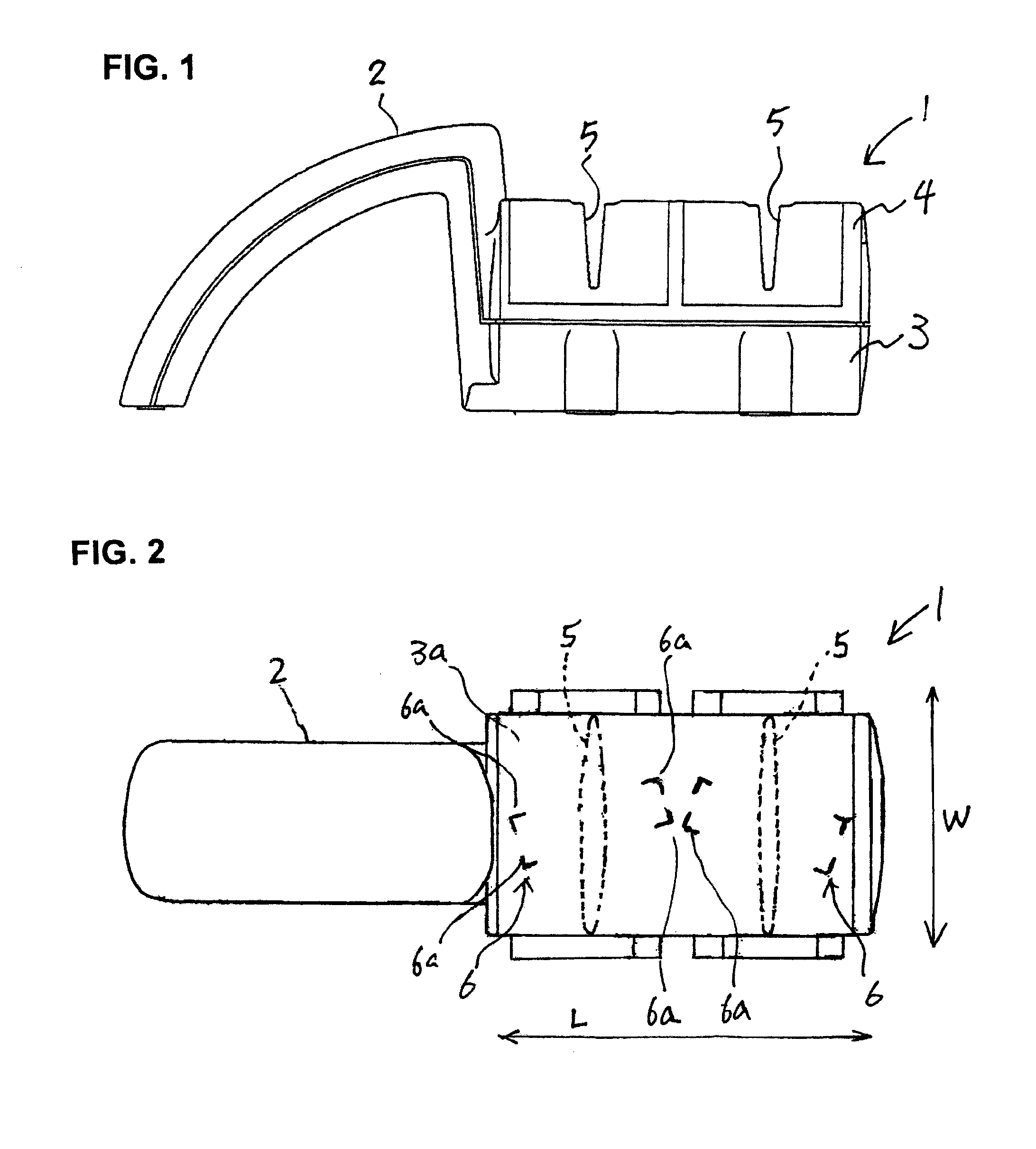
[0042]FIGS. 1 and 2 illustrate an example of a frame casing body 1 of the blade sharpener according to the present invention. The frame casing body 1 is made of, for instance, synthetic resin and includes a grip 2 and a grinding chamber 3 which is connected to the end of the grip 2 and is substantially in a rectangular box shape having a size of for instance 2.5 inches (W)×4 inches (L)×2.5 inches (H). The grinding chamber 3 is provided with a removable cover, casing 4 covering the upper opening of the grinding chamber 3, and this removable cover casing 4 is formed with two blade guide slits 5 which extend in the width direction W of the grinding chamber 3 so as to open continuously to the above and to both sides of the cover casing 4.

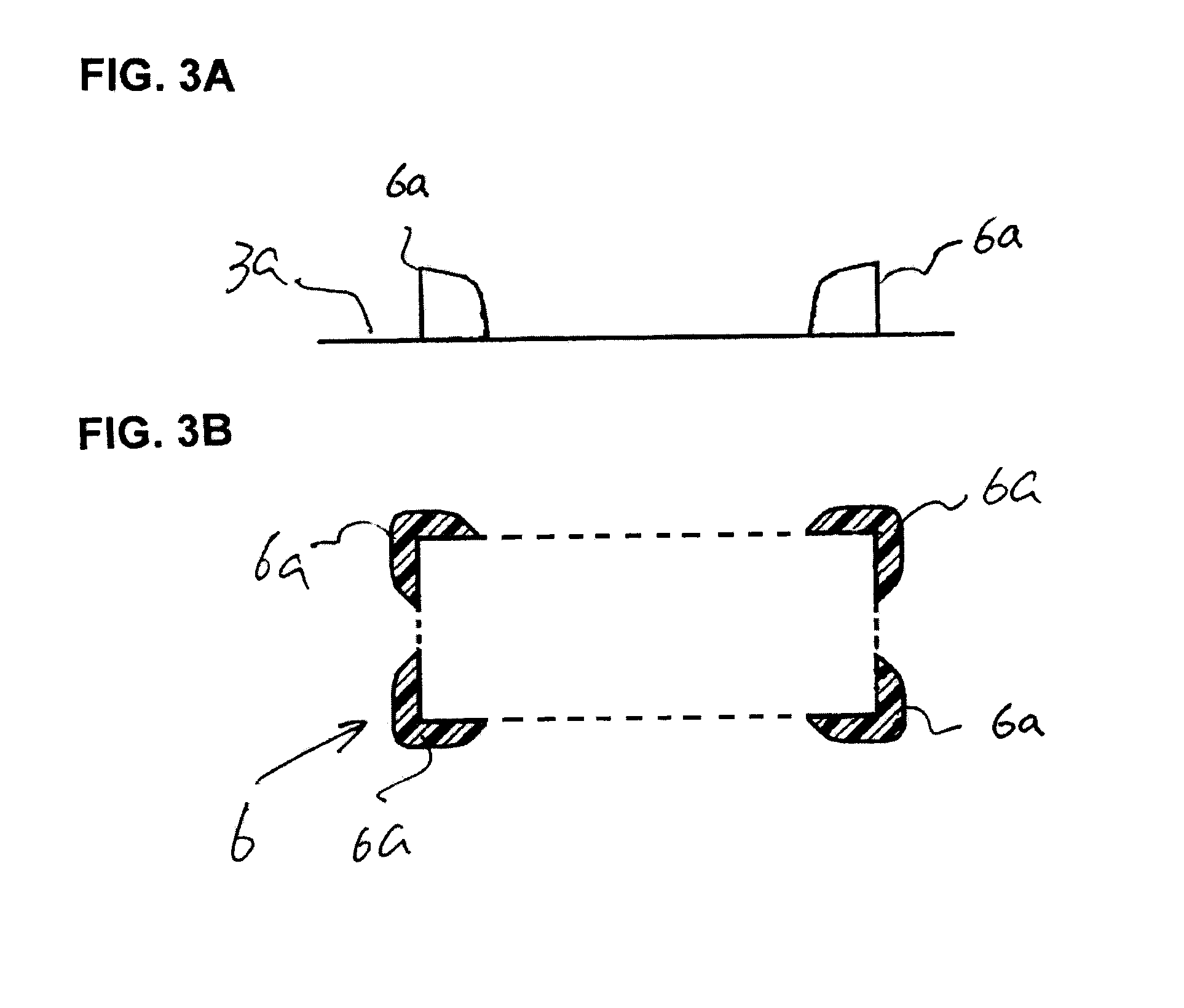
[0043]On the rectangular bottom 3a of the grinding chamber 3, one pair of (or two) holding ...


PUM

PropertyMeasurementUnit
sizeaaaaaaaaaa
diagonal angleaaaaaaaaaa

Abstract

A blade sharpener including a frame casing body having a grip and a grinding chamber and a grinder assembly detachably installed in the grinding chamber in which the grinder assembly is formed by a grinder casing body having a pair of vertical walls facing each other, a supporting window provided in each of the vertical walls, a rotary shaft provided between the vertical end walls with both end thereof in the supporting windows of the vertical walls, an abrasive wheel provided on the rotary shaft at the axial center, and a pair of lateral coil springs each provided on either side of the abrasive wheel. The rotary shaft can be supported by a pair of longitudinal coil springs installed in the vertical walls.

Description

BACKGROUND OF THE INVENTION[0001]1. Field of the Invention[0002]The present invention relates to a blade sharpener that sharpens blades such as kitchen knives and table knives with an abrasive wheel and more particularly to a manual blade sharpener having an abrasive wheel therein.[0003]2. Background Art[0004]Japanese Patent Application Laid-Open (Kokai) No. S62-181860 discloses a table knife sharpener that is comprised of a frame casing body, a adhesive wheel rotatably installed in this frame casing body and equipped with grinding surfaces that are of a truncated cone shape and forming an angle to each other, a guide part that guides the blade so that the blade being sharpened is pressed against both grinding surfaces, and a liquid vessel installed in the frame casing body so as to surround the bottom part of the abrasive wheel.[0005]In this device, two sides of the blade of a knife is pressed against the two sides of the grindstone and the knife is moved back and forth at a bias r...

Claims


Application Information

Patent Timeline
Patent Type & Authority Applications(United States)
IPC IPC(8): B24B3/36
CPCB24D15/082
Inventor HASEGAWA, TOM HIROSHI
Owner HASEGAWA TOM HIROSHI
Why Eureka
Try Eureka