Liquid crystal display device

a liquid crystal display and display screen technology, applied in the field can solve the problems of display defects, low alignment stability, and difficulty in adjusting the viewing angle of liquid crystal display devices, and achieve the effects of reducing the time constant of dc, improving the afterimage characteristics of photoalignment films, and improving the viscosity of varnishes

Active Publication Date: 2013-11-14
JAPAN DISPLAY INC
View PDF1 Cites 5 Cited by
  • Summary
  • Abstract
  • Description
  • Claims
  • Application Information

AI Technical Summary

Benefits of technology

The invention is about a liquid crystal display device that can reduce the time it takes for images to appear after being displayed, while also improving the alignment stability and reliability of the display. This is achieved by using a special material made up of two components that are separated from each other. One component provides high alignment stability, while the other component reduces the resistance to the flow of electric current in the display. This results in improved image quality. Additionally, the invention allows for a thicker alignment film, which would have been difficult to achieve in previous methods.

Problems solved by technology

On the other hand, viewing angle characteristics of liquid crystal display devices are a problem.
However, it is known that, in regard to the point of imparting alignment control ability to the alignment film, alignment stability is usually lower in photoalignment in comparison to alignment stability in rubbing.
When alignment stability is low, the initial alignment direction fluctuates, which leads to display defects.
Particularly in liquid crystal display devices that use an in-plane switching liquid crystal display panel where high alignment stability is demanded, it is easy for display defects symbolized by afterimages to occur as a result of alignment stability being low.
The liquid crystal molecules align along the direction of the long main chain that remains extending on a straight line without being broken, but when the length of this main chain becomes short, uniaxiality drops, interaction with the liquid crystal becomes weak and alignment deteriorates, so it becomes easy for afterimages to occur.

Method used


Image

  • Liquid crystal display device
  • Liquid crystal display device
  • Liquid crystal display device

Examples


embodiment 1

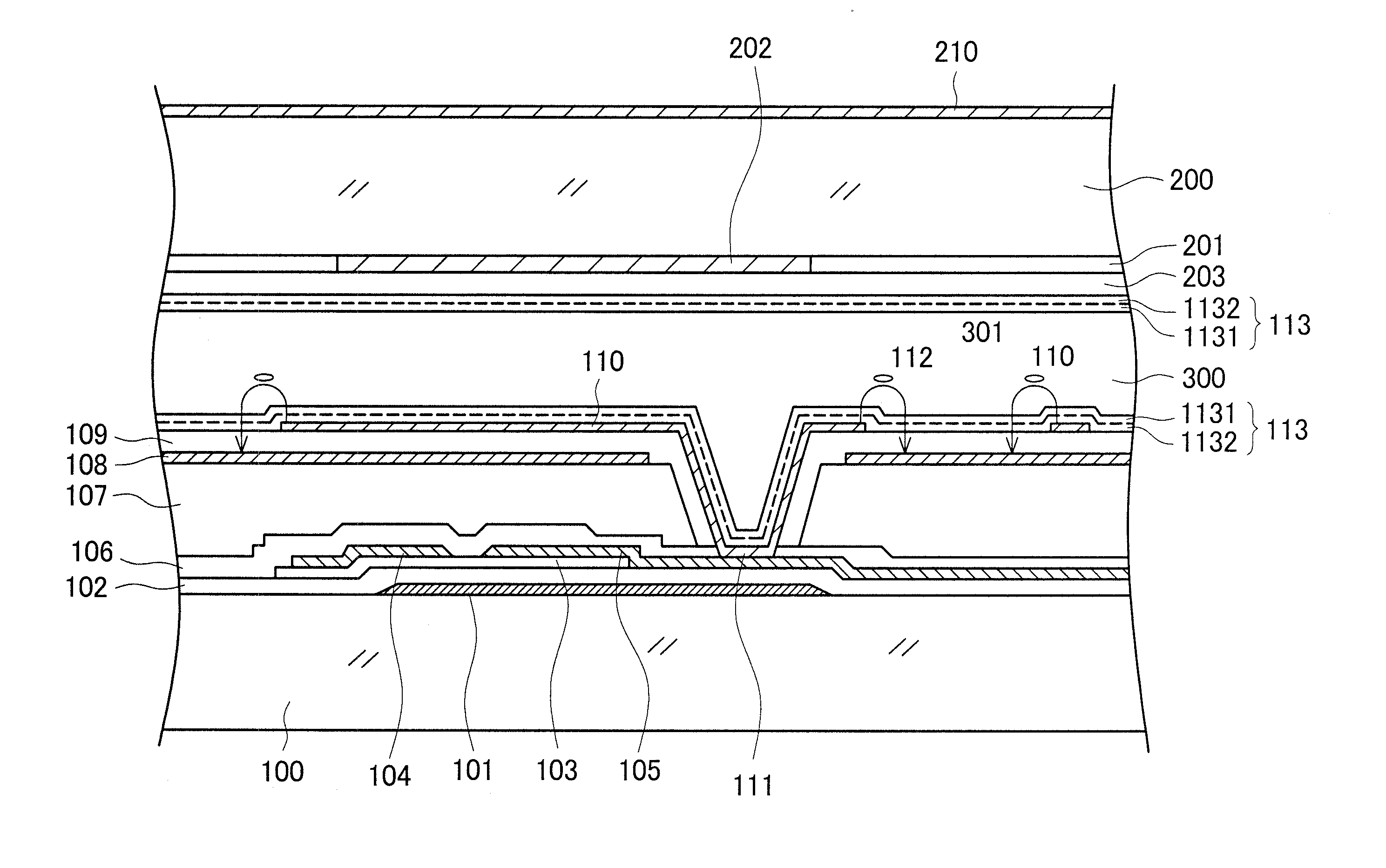
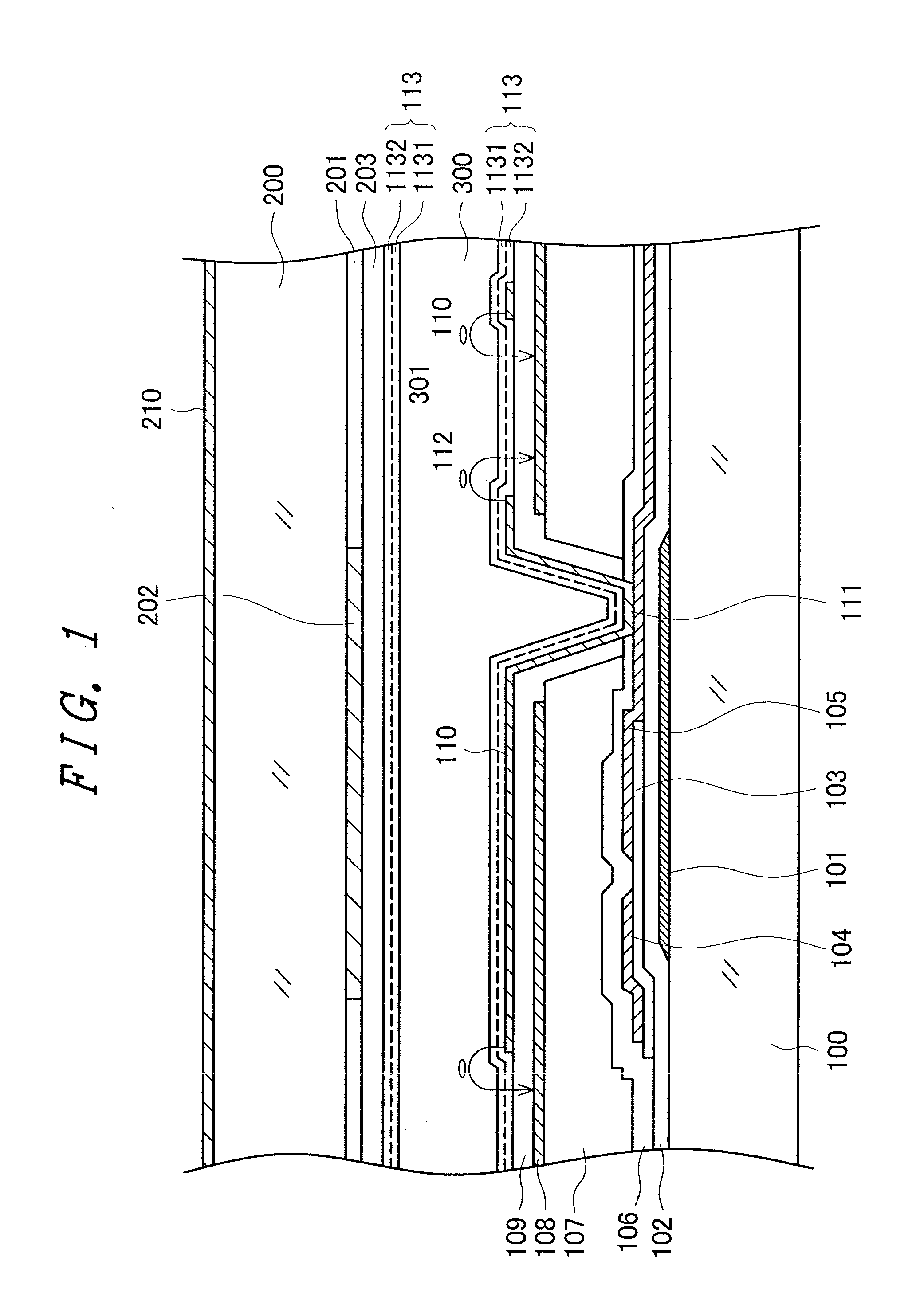
[0030]FIG. 1 is a cross-sectional diagram showing a structure in a display region of an IPS liquid crystal display device. Various structures are being proposed and put to practical use for the electrode structure of IPS liquid crystal display devices. The structure in FIG. 1 is a structure that is currently being widely used; simply put, a pectinate pixel electrode 110 is formed on an opposing electrode 108 formed in a flat solid, with an insulating film sandwiched between the pixel electrode 110 and the opposing electrode 108. Additionally, the liquid crystal display device forms an image by controlling the transmittance of light through a liquid crystal layer 300 per pixel by causing liquid crystal molecules 301 to be rotated by a voltage between the pixel electrodes 110 and the opposing electrodes 108. The structure in FIG. 1 will be described in detail below. It will be noted that, although the invention will be described taking the structure in FIG. 1 as an example, the invent...

embodiment 2

[0073]In embodiment 1, a film obtained by imidizing the polyamide acid is used as the low-resistivity alignment film 1132 on the bottom of the 2-layer alignment film 113. The low-resistivity alignment film 1132 has no relationship with photoalignment, so a material can be selected focusing on making the resistance of the alignment film 113 small.

[0074]In liquid crystal display devices, a backlight is disposed on the back surface of the liquid crystal display panel, and an image is formed by controlling the light from the backlight per pixel. A cold-cathode tube or a light-emitting diode is used as the light source of the backlight. Consequently, the alignment film 113 becomes always exposed to the light from the backlight while the liquid crystal display device is operating. When a photoconductive film is used as the low-resistivity alignment film 1132 on the bottom, the electric charge with which the liquid crystal layer has been charged can be let out more quickly, and DC afterima...


PUM

PropertyMeasurementUnit
image contrastaaaaaaaaaa
carbon numberaaaaaaaaaa

Abstract

An alignment film is given a 2-layer structure comprising a photoalignment film that is photoalignable and a low-resistivity alignment film whose resistivity is smaller than that of the photoalignment film. The photoalignment film is formed by a polyimide whose precursor is polyamide acid alkyl ester, the number molecular weight of the photoalignment film is large, and the stability of alignment of the photoalignment film by photoalignment is excellent. The low-resistivity alignment film is formed by a polyimide whose precursor is polyamide acid, the number molecular weight of the low-resistivity alignment film is small, and the resistivity of the low-resistivity alignment film is small. The 2-layer structure alignment film can be maintaining an excellent photoalignment characteristic, so DC afterimages can be controlled.

Description

CROSS-REFERENCE TO RELATED APPLICATION[0001]This application is a continuation application of U.S. application Ser. No. 12 / 560,770 filed Sep. 16, 2009, the contents of which are incorporated herein by reference.CLAIM OF PRIORITY[0002]The present application claims priority from Japanese application serial No. 2008-235900, filed on Sep. 16, 2008, the content of which is hereby incorporated by reference into this application.BACKGROUND[0003]1. Technical Field[0004]The present invention pertains to a liquid crystal display device and particularly relates to a liquid crystal display device that is equipped with a liquid crystal display panel where alignment control ability is imparted to an alignment film by irradiation with light.[0005]2. Related Art[0006]Liquid crystal display devices have a TFT substrate on which pixel electrodes and thin film transistors (TFTs) are formed in a matrix, an opposing substrate that opposes the TFT substrate and on which color filters are formed in place...

Claims


Application Information

Patent Timeline
Patent Type & Authority Applications(United States)
IPC IPC(8): G02F1/1337
CPCG02F1/133723G02F1/133788B32B2457/202C09K2323/025C09K2323/027C09K2323/035C09K2323/00G02F1/133397C09K19/56G02F1/134363G02F1/13439
Inventor MATSUI, CHIKAEKUNIMATSU, NOBORUSONODA, HIDEHIRO
Owner JAPAN DISPLAY INC
Why Eureka
Try Eureka