
Data processing apparatus having cache and translation lookaside buffer

a data processing apparatus and cache technology, applied in the field of data processing, can solve the problems of increasing the energy efficiency of the memory subsystem, exacerbate the problem, and increase the cost of processing, so as to achieve the effect of efficient system accessing the cache and facilitating copy operations

Active Publication Date: 2013-11-14
ARM LTD
View PDF12 Cites 113 Cited by
  • Summary
  • Abstract
  • Description
  • Claims
  • Application Information

AI Technical Summary

Benefits of technology

The patent text describes a cache system that can efficiently store and access data. It uses a cache with multiple cache lines and a way table to determine which cache line will store a requested data. The system also selects one bank to service requests that target the same cache line, which improves performance. The technical effect of this system is improved efficiency and performance by optimizing cache accesses and reducing the processing load on the cache.

Problems solved by technology

This problem is exacerbated by advanced memory speculation and disambiguation techniques, which are fairly common in the latest generation of microprocessors, and by vector extensions, like Intel AVX and ARM NEON, which provide support for the SIMD computation paradigm and can introduce even more demanding requirements for the memory subsystem.
However, finite energy sources and limitations in semiconductor technology scaling result in fixed energy budgets for mobile devices; in addition, cooling and electricity costs are becoming increasingly important in the desktop and server segments.
As a consequence, energy efficiency has become a determining factor for microprocessor designs and one of the main obstacles to performance improvements.
As caches are one of the main contributors to the on-chip power consumption, cache-level optimisations need to trade-off increased performance with degraded energy efficiency.
The former technique is based on modified SRAM cells with multiple ports; it allows low access latencies, but introduces large energy and area penalties.
However, these designs require a significant amount of dedicated hardware, and the implemented solutions, while effective on workloads with abundant data-level parallelism, are not suited for general-purpose microprocessors.
While this concept is simple to implement, false predictions require a second cache access to find the desired datum within the previously discarded ways.
Consequently, cache accesses require no more than one cycle, but may consume energy for several redundant tag comparisons.
Consequently, it is limited to systems with high temporal locality of cache accesses designed to service a low number of loads and stores in parallel.
However, the increased complexity of such circuitry would require more energy and time per cycle.
The cache itself is unmodified to allow the implementation of highly optimized designs.
However, this would complicate the execution of address translation and data access in separate pipeline stages as it is common for high performance processors.
The amount of speculative state held by MALEC itself is limited to loads within the Input Vector and the Arbitration Unit.
Furthermore, the finite number of TLB entries might require the eviction of a page that still has corresponding lines within the cache.
Reasons for this are large working sets combined with low locality leading to high miss rates that do not benefit from faster L1 accesses.
Second, all WDU configurations cover significantly less memory accesses than way tables (see FIG. 22), and therefore suffer the energy penalty of an increased number of “conventional” instead of “reduced cache accesses” (see Section 5).
However, while the energy consumption of way tables are widely unaffected by the desired number of parallel memory accesses, the WDU does not scale well.
However, this effectively reduces the uWT's coverage, which increases the dynamic energy consumed due to more WT accesses.

Method used


Image

  • Data processing apparatus having cache and translation lookaside buffer
  • Data processing apparatus having cache and translation lookaside buffer
  • Data processing apparatus having cache and translation lookaside buffer

Examples


Embodiment Construction

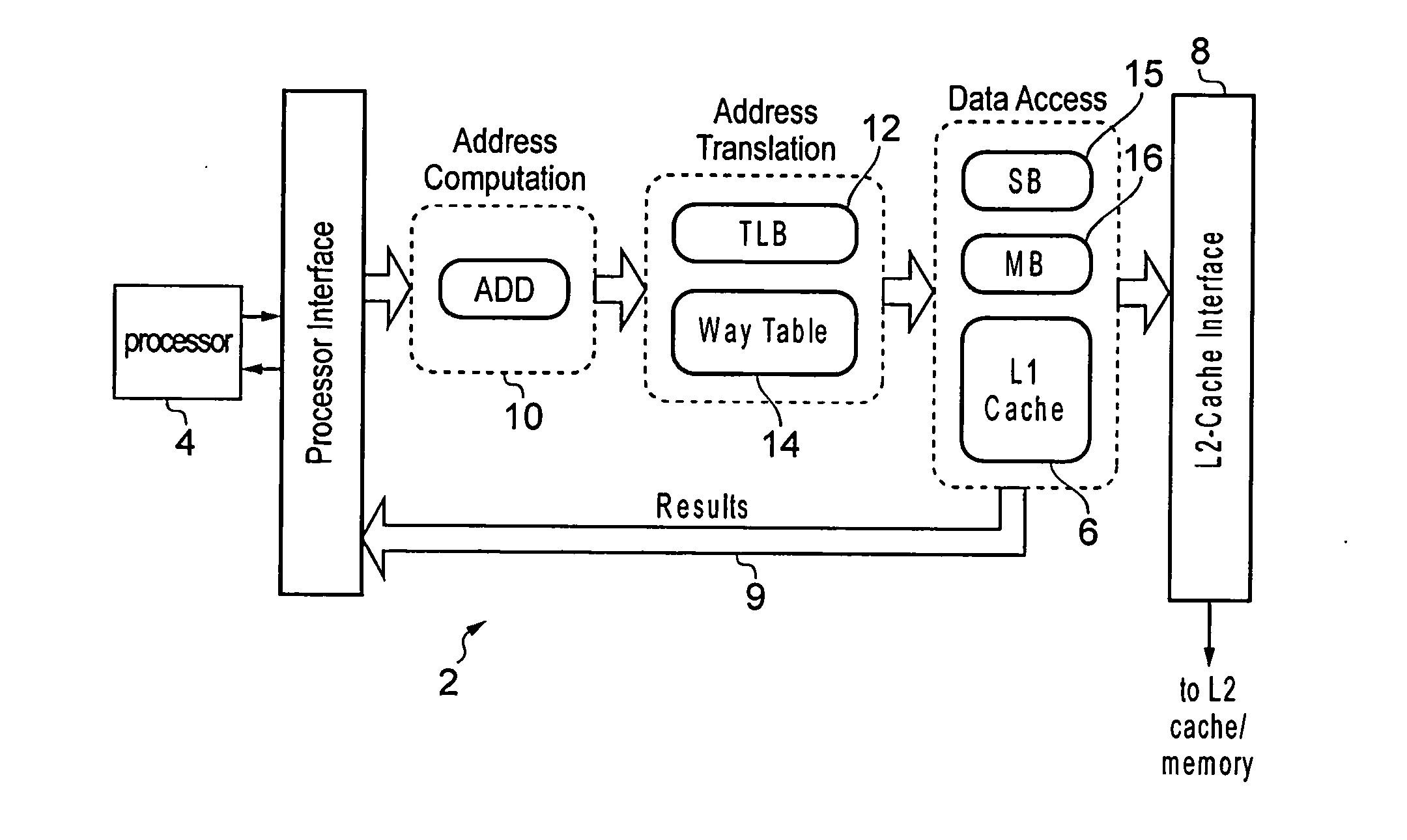
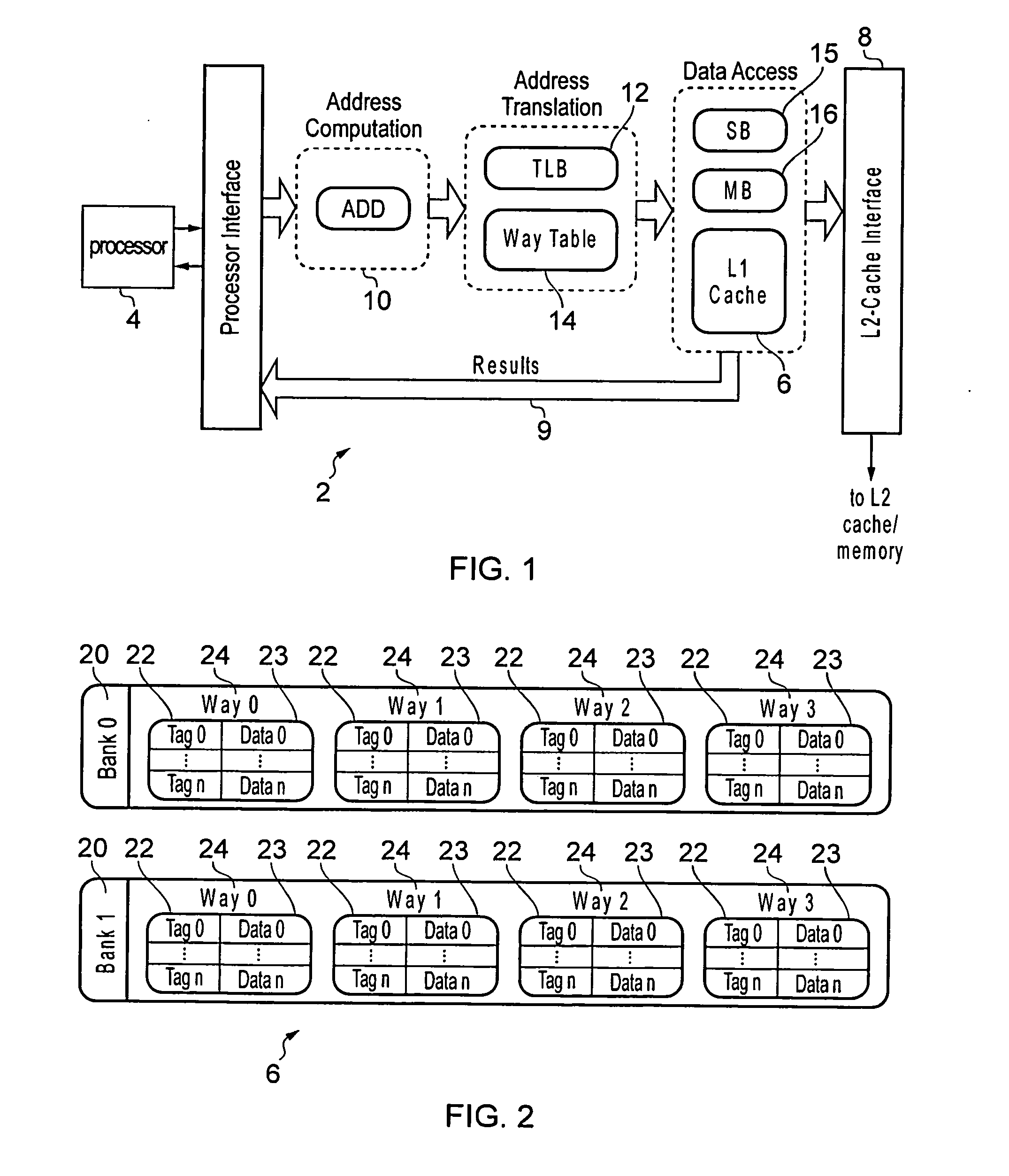
[0115]FIG. 1 schematically illustrates a data processing apparatus 2 comprising a processor 4 for processing data. A cache 6 is provided for storing data on behalf of the processor 4. The cache 6 is a level 1 (L1) cache which is a member of a cache hierarchy including at least one further level cache (the L2 cache). The L1 cache 6 communicates with the L2 cache and with a memory (not shown in FIG. 1) via an L2-cache interface 8. If data required by the processor 4 is not present in the L1 cache 6, then the L1 cache 6 requests the data from the L2 cache or the memory and allocates the data to a line of the cache 6. A cache coherency policy (e.g. write-back or write-through policy) may be used to maintain coherency of data in the L1 cache 6, L2 cache and memory. A bus 9 is provided for returning results of serviced cache accesses to the processor 4.

[0116]The processor 4 may issue data access requests for accessing data from the cache 6. An address computation stage 10 is provided for ...


PUM


Abstract

A data processing apparatus has a cache and a translation look aside buffer (TLB). A way table is provided for identifying which of a plurality of cache ways stores require data. Each way table entry corresponds to one of the TLB entries of the TLB and identifies, for each memory location of the page associated with the corresponding TLB entry, which cache way stores the data associated with that memory location. Also, the cache may be capable of servicing M access requests in the same processing cycle. An arbiter may select pending access requests for servicing by the cache in a way that ensures that the selected pending access requests specify a maximum of N different virtual page addresses, where N<M.

Description

BACKGROUND OF THE INVENTION[0001]1. Field of the Invention[0002]The present invention relates to the field of data processing. More particularly, the invention relates to a data processing apparatus having a cache and a translation lookaside buffer.[0003]2. Description of the Prior Art[0004]A data processing apparatus may have a cache for storing data. The cache provides more rapid access to a portion of the data stored in a memory. A data processing apparatus may also comprise a translation lookaside buffer (TLB) for translating between virtual addresses specified by the processor and physical addresses used by the cache and / or memory. If the cache is a physically indexed or physically tagged cache, then an address translation is required using the TLB before a cache access can be made. Even if the cache is virtually indexed and virtually tagged, a TLB translation may still be required to access memory.[0005]The present technique seeks to improve the energy efficiency of performing...

Claims


Application Information

Patent Timeline
IPC IPC(8): G06F12/08
CPCG06F12/1054G06F12/1027G06F2212/1028G06F2212/6082G06F12/0864Y02D10/00
Inventor BOTTCHER, MATTHIAS LOTHARKERSHAW, DANIEL
Owner ARM LTD
Learn More