
System and method for sensor-less hysteresis current control of permanent magnet synchronous generators without rotor position information

a permanent magnet synchronous generator and sensorless technology, applied in the direction of motor/generator/converter stopper, electronic commutator, dynamo-electric converter control, etc., can solve the problems of reducing the capacity of the generator, limiting the application of the microcontroller system, and complex implementation with the microcontroller system, so as to achieve better generator control and robust and efficient

Inactive Publication Date: 2013-11-21
MAGDRIVE
View PDF2 Cites 1 Cited by
  • Summary
  • Abstract
  • Description
  • Claims
  • Application Information

AI Technical Summary

Benefits of technology

The present invention provides a method for controlling a permanent magnet generator without using position sensors to detect the position of the rotor relative to the stator. This is done by measuring current and phase voltage zero-crossing events to feed back into the generator to control its output. A synchronization sequence is used to detect the zero-crossing event and control the generator using current hysteresis control, which is non-predictable and depends on the load on the generator. This method eliminates the need for costly position sensors and simplifies the control system of generators. A microcontroller with input / output ports is used for defining feedback signal readings and operating power switches that control the output voltage of the generator. The overall effect is improved efficiency and control of permanent magnet generators without the need for costly position sensors.

Problems solved by technology

This type of control has a drawback in that it is complex to implement with microcontroller systems as it requires rotor position information, an analog-to-digital converter and a powerful microcontroller that needs to have as high a switching frequency as possible in order to achieve low-ripple current waveform.
This aspect of the control, limits its application to situations where loads do not vary widely, as the reaction time of the control is quite slow, albeit simple and thus suitable for microcontroller based systems.
The problem with all of the existing systems is that the permanent magnet generator is not optimally controlled, because phase current and back EMF are not aligned, due to lack of current control and the rotor position feedback techniques result in excessive reactive power use thereby reducing the capacity of the generator and making the generator prone to over-heating.

Method used


Image

  • System and method for sensor-less hysteresis current control of permanent magnet synchronous generators without rotor position information
  • System and method for sensor-less hysteresis current control of permanent magnet synchronous generators without rotor position information
  • System and method for sensor-less hysteresis current control of permanent magnet synchronous generators without rotor position information

Examples


Embodiment Construction

[0020]Generally, the systems, components and methods described herein for providing sensor-less hysteresis current control of PM generators according to the present invention may be implemented in a variety of hardware, software or combinations thereof.

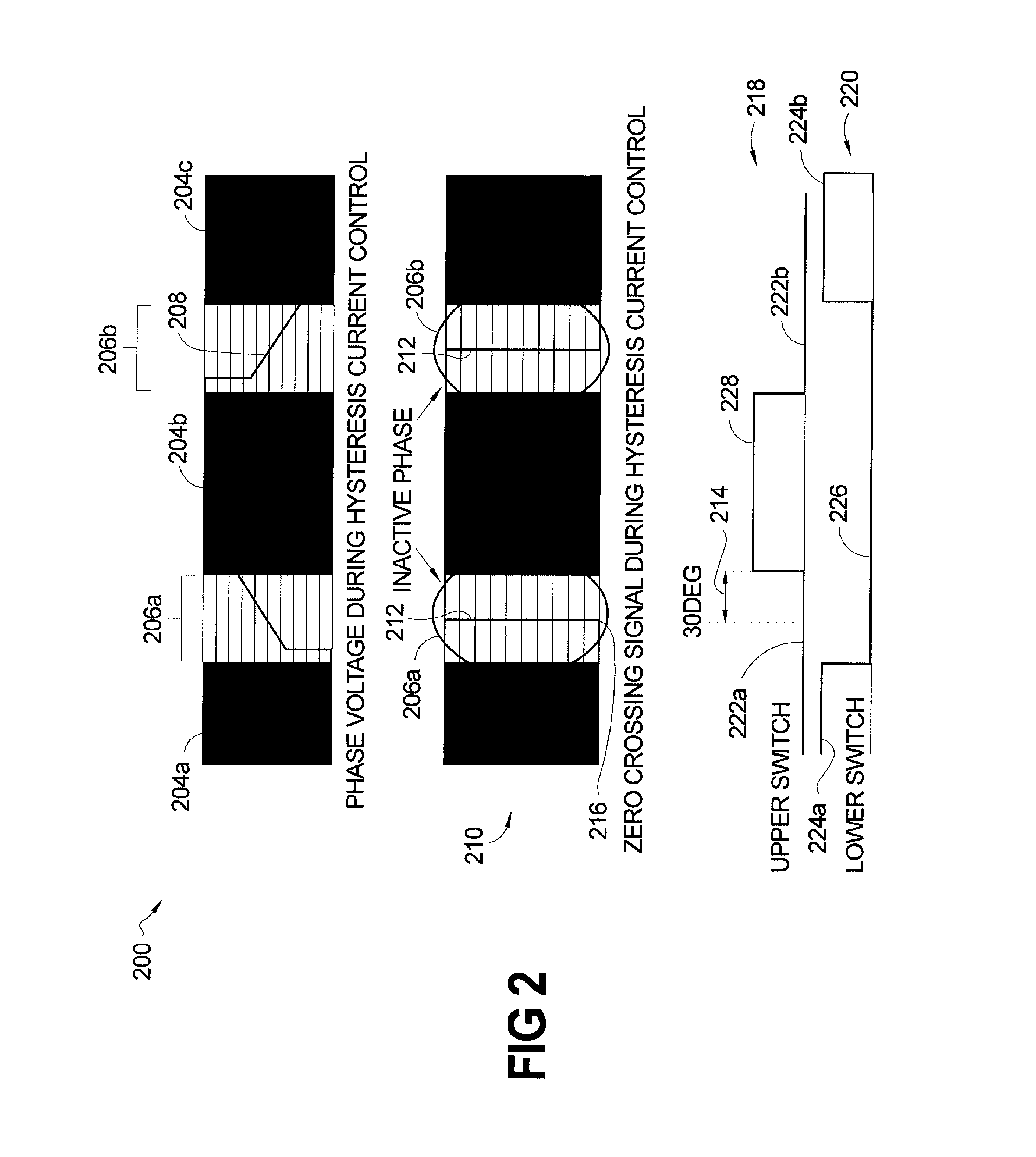
[0021]The present invention applies the six-step BLDC switching scheme and controls the current and torque of the PM generator without obtaining continuous information / feedback signals of the rotor position relative to the stator of the generator. The sensor-less hysteresis current control concept of the present invention features two components namely, a zero-crossing algorithm and a switching pattern.

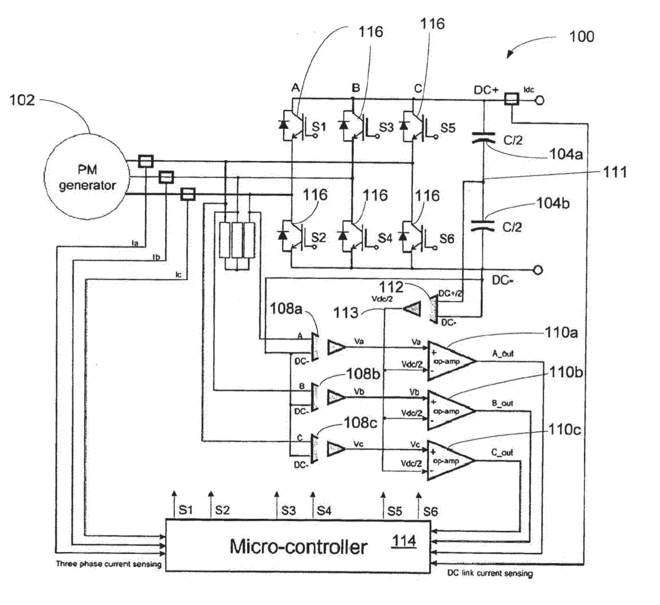
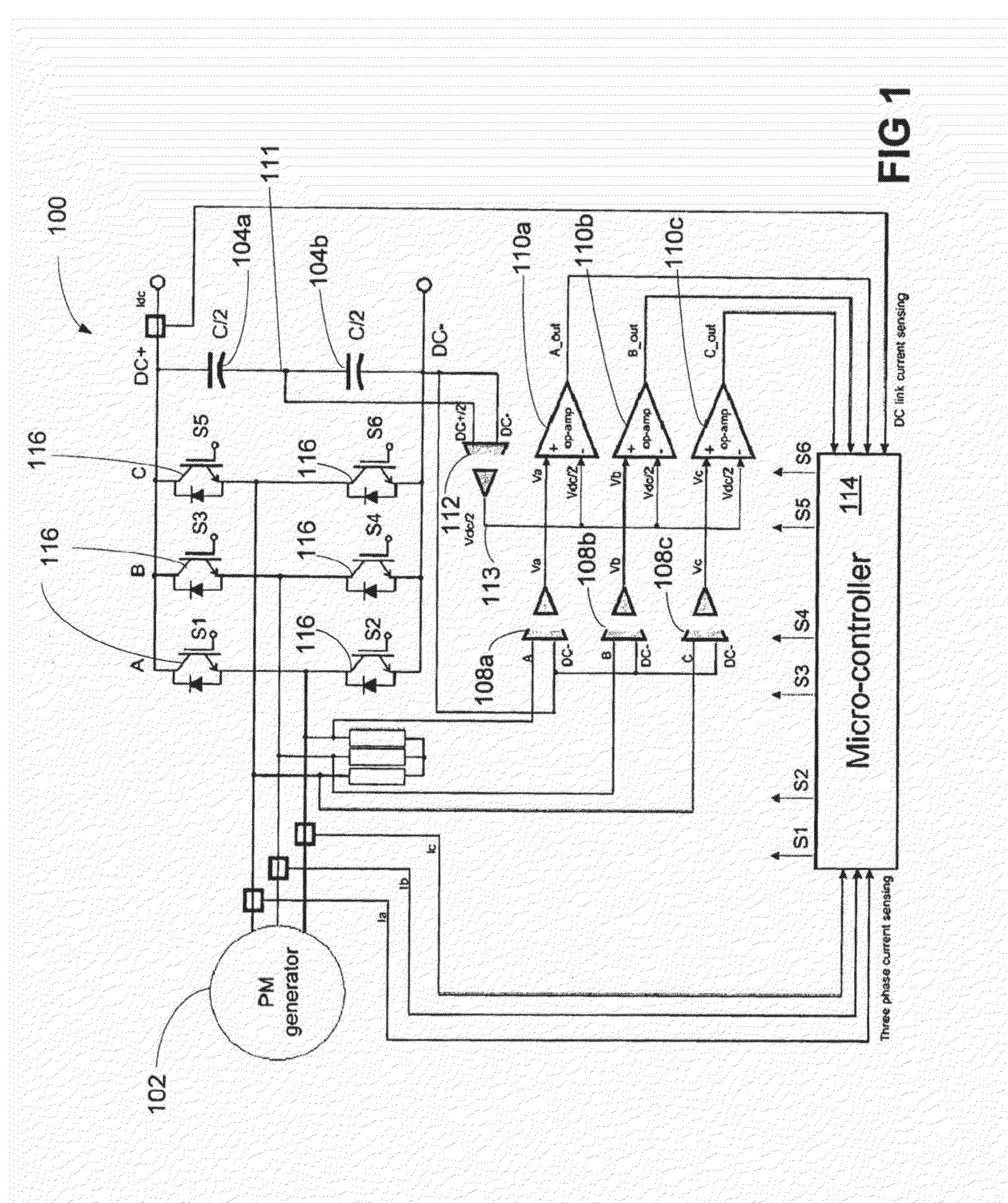
[0022]An exemplary hardware configuration for implementing the control concept of the present invention is illustrated in FIG. 1. The system 100 comprises a permanent magnet generator 102, which is a three phase (A, B, C) machine having a rotor with permanent magnets. The phases A, B, C of the generator 102 are connected to power switch...


PUM


Abstract

A system and method are provided for controlling a permanent magnet synchronous generator without rotor position information, utilizing sensor-less hysteresis control and brushless direct current switching scheme. The present invention controls the current and torque of the permanent magnet generator without information of the rotor position in respect to the stator.

Description

FIELD OF THE INVENTION[0001]The present invention generally relates to a system and method for providing sensor-less hysteresis current control of permanent magnet synchronous generators without information of rotor position. In operation, a zero-crossing algorithm in conjunction with a switching pattern is utilized to control a permanent magnet generator.BACKGROUND OF THE INVENTION[0002]There is a wide spread use of brushless direct current three-phase motors in applications wherein reliability and high efficiency are required. Critical to the operation and use of brushless motors is driving and controlling the motors to effectively reduce variations from one revolution to the next thus making the output of the PM machines more stable, efficient and precise.[0003]Permanent magnet brushless electrical machines, have a permanent magnet rotor and a stator comprising a plurality of phase winding that may be independent or coupled in a variety of configurations. Typically, brushless ele...

Claims


Application Information

Patent Timeline
Patent Type & Authority Applications(United States)
IPC IPC(8): H02P6/14
CPCH02P6/182H02P9/009
Inventor GURKAYNAK, YUSUFSTAMENKOVIC, IGORMILIVOJEVIC, NIKOLASCHOFIELD, NIGELBAROUD, ANTHONY J.
Owner MAGDRIVE
Learn More