
Method for improving performance of filter and power conversion apparatus

a technology of power conversion apparatus and filter, which is applied in the direction of reducing harmonics/ripples in dc circuits, dc network circuit arrangements, and efficient power electronics conversion, etc. it can solve the problems of reducing the performance and filtering emi filter cannot operate normally, and emi filter interference with an input of the power converter, so as to improve the performance of the filter and enhance the effect of the emi filter

Active Publication Date: 2013-11-21
DELTA ELECTRONICS INC
View PDF3 Cites 12 Cited by
  • Summary
  • Abstract
  • Description
  • Claims
  • Application Information

AI Technical Summary

Benefits of technology

The present application provides a method for improving the performance of an EMI filter in a power converter. This is achieved by using an energy-storage magnetic component and a two-port network connected between them. By adjusting the frequency at which the insertion loss of the filter needs to be improved, the coupling between the energy-storage magnetic component and the inductor component can be adjusted to form a series resonance, which results in a mutual inductance and a reduction in interference with the EMI filter from the energy-storage magnetic component. This helps to improve the performance and effectiveness of the EMI filter and avoid the need for expensive and larger filters.

Problems solved by technology

Harmonic voltage and harmonic current generated by on-off actions of a switch component in a power converter may cause electromagnetic interference with an input of the power converter.
As the power density of a power converter is increased, the volume of a power converter is reduced, and the distance between devices or between components is lessened, energy-storage magnetic components in the power converter, such as a transformer or an inductor component, may cause interference with an EMI filter, thereby the EMI filter cannot operate normally, or the performance and filtering effect of the EMI filter are reduced.
However, the following defects exist in the above method:1. The volume and cost of an EMI filter may be increased.2. The filtering for strong electromagnetic interference at specific frequencies can not be efficiently directed.

Method used


Image

  • Method for improving performance of filter and power conversion apparatus
  • Method for improving performance of filter and power conversion apparatus
  • Method for improving performance of filter and power conversion apparatus

Examples


Embodiment Construction

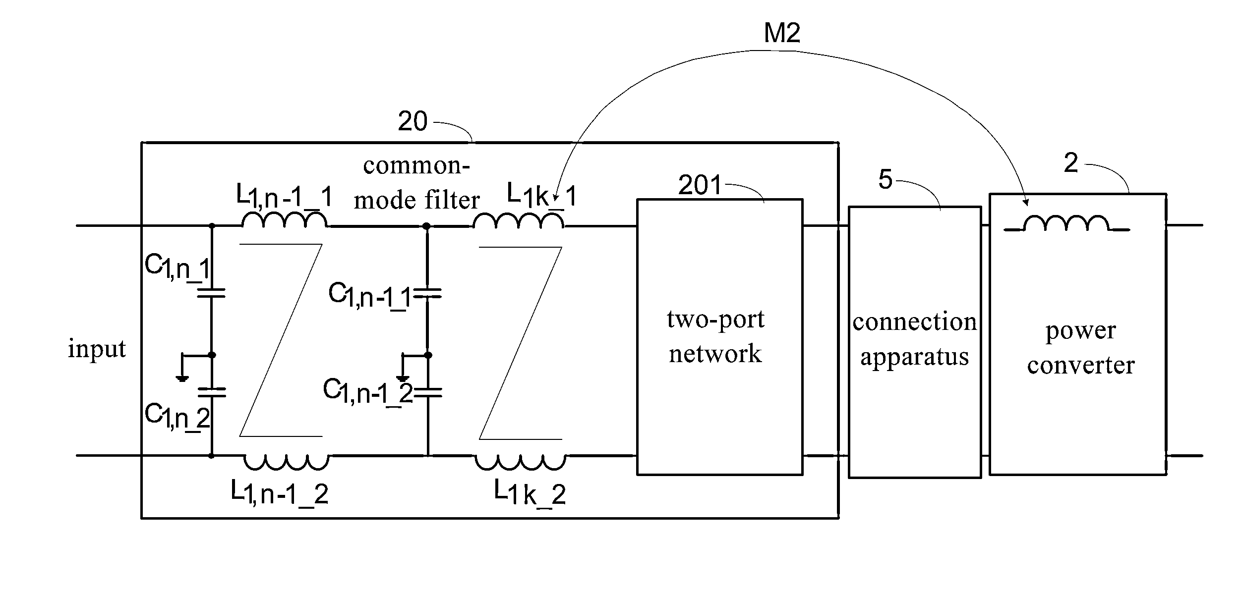
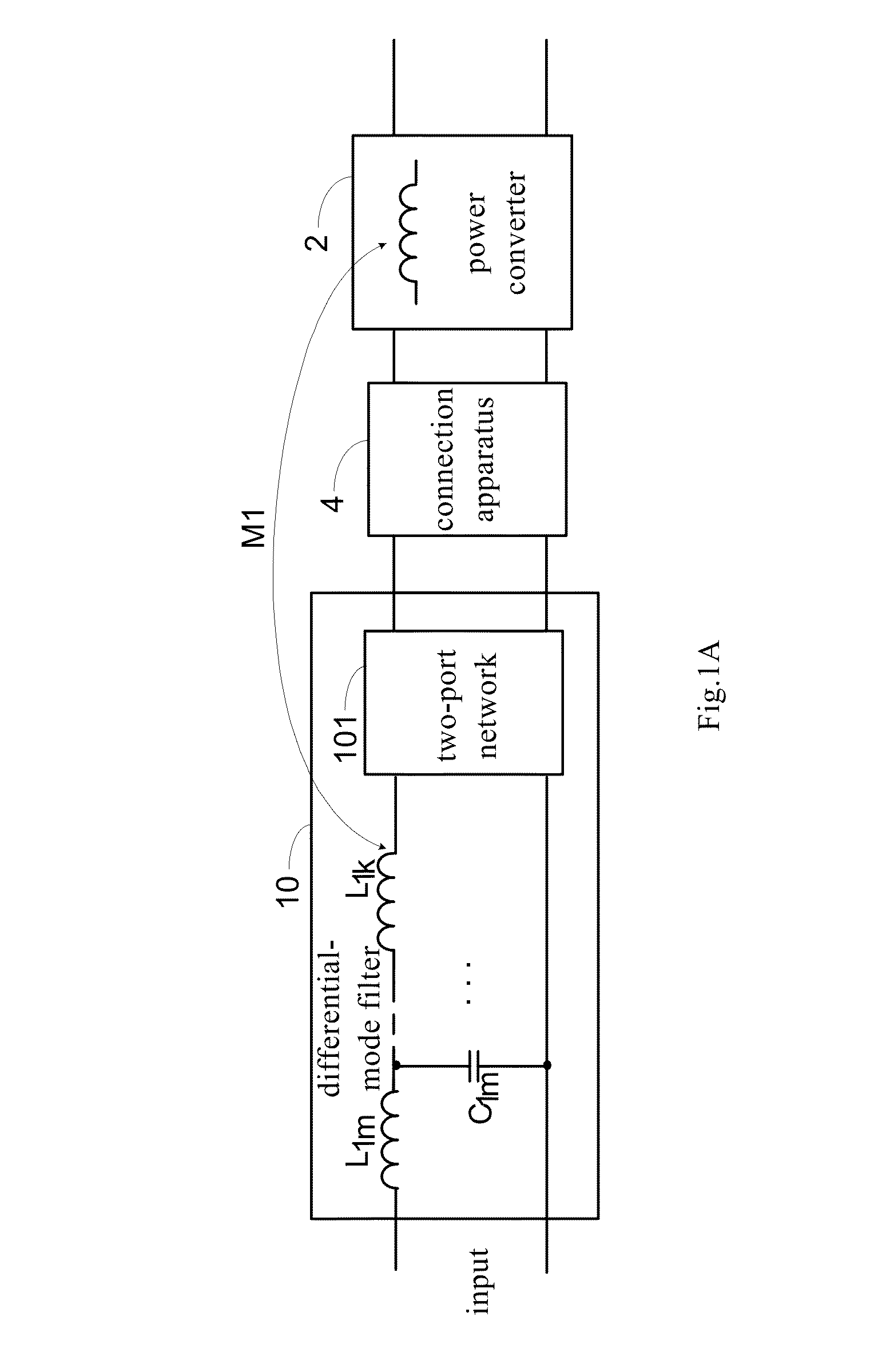
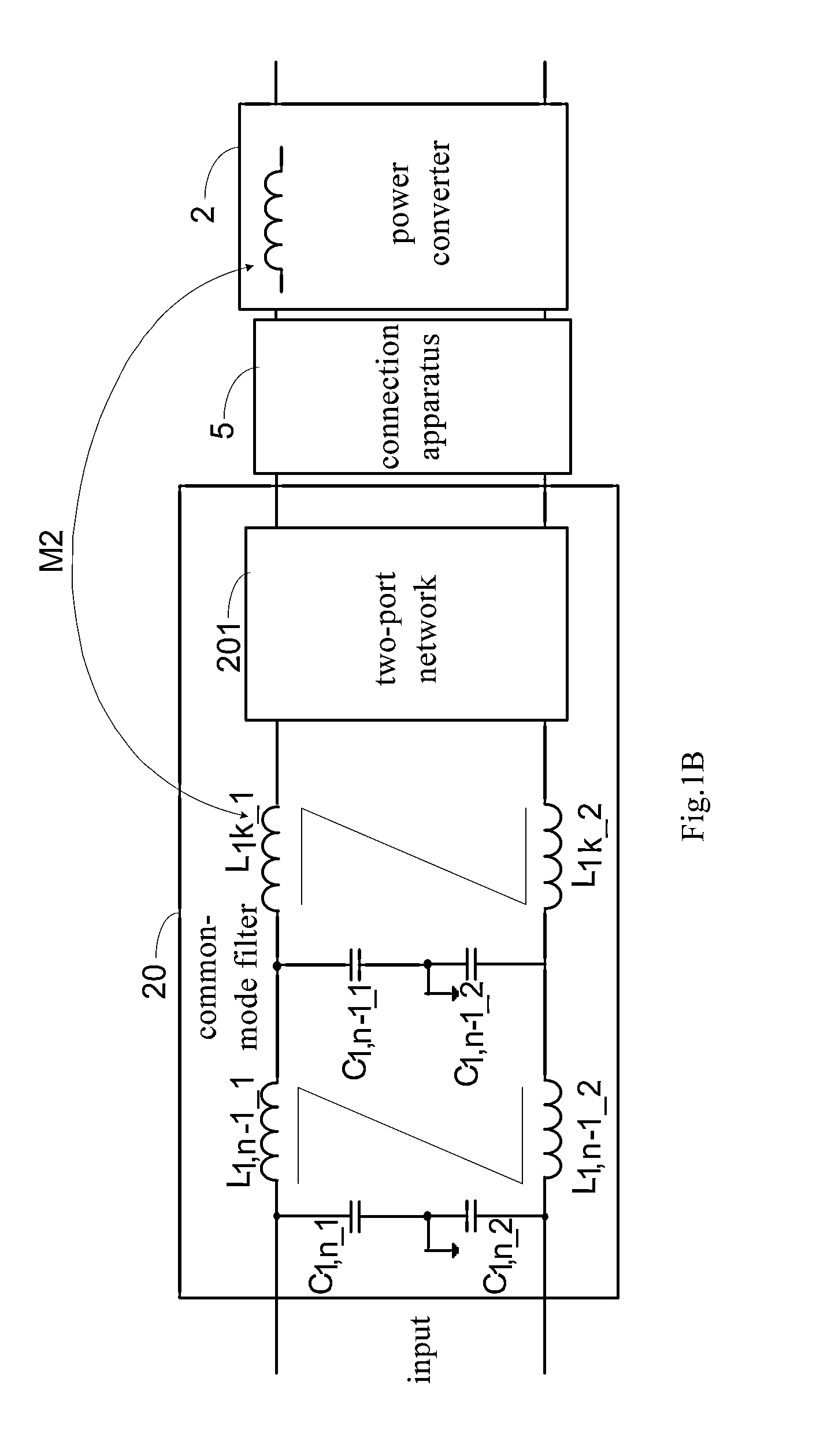
[0036]Hereinafter, the present application will be described in detail with reference to FIGS. 1A-12B. It should be noted that, in the accompanying drawings described hereinafter, when a cross point existing between line sections (as connecting wires) is a black point, the cross point represents a junction, and when a cross point existing between the line sections is not a black point, the cross point is not a junction but represents that the line sections are only across each other. Turns shown in each winding are illustrative and do not represent the real turns or turns ratio. Each sign of inductor, transformer winding and capacitor represents not only the component itself but also an algebra character of the capacity thereof. In the embodiments and claims, “a” and “the” indicate one or more, unless the context defines otherwise.

[0037]FIG. 1A is a circuit diagram exemplarily showing an embodiment of a power conversion apparatus comprising an EMI differential-mode filter and a powe...


PUM


Abstract

A power conversion apparatus is disclosed in the present application. The power conversion apparatus comprises: a power converter comprising an energy-storage magnetic component, and a filter comprising an inductor component and a two-port network connected the energy-storage magnetic component and the inductor component, wherein a series resonance is formed by the two-port network and a mutual inductance which is formed by a coupling between the energy-storage magnetic component and the inductor component.

Description

CROSS REFERENCE TO RELATED APPLICATIONS[0001]The present application claims priority under 35 U.S.C. §119 to Chinese Patent Application No. 201210156306.7, filed on May 18, 2012, the entire content of which is incorporated herein by reference.FIELD OF THE INVENTION[0002]The present application relates to a method for improving performance of a filter and the power conversion apparatus thereof.BACKGROUND OF THE INVENTION[0003]Harmonic voltage and harmonic current generated by on-off actions of a switch component in a power converter may cause electromagnetic interference with an input of the power converter. Therefore, an EMI (Electromagnetic Interference) filter is generally needed to be provided between the power converter and the input in order to reduce the electromagnetic interference with the input.[0004]As the power density of a power converter is increased, the volume of a power converter is reduced, and the distance between devices or between components is lessened, energy-s...

Claims


Application Information

Patent Timeline
Patent Type & Authority Applications(United States)
IPC IPC(8): H02J1/02H02M1/00H02M1/44
CPCH02M1/126H02M1/14H02M1/44H02M3/158H02M3/33523H02M1/0064Y02B70/10
Inventor WU, RUIXIE, YICONGZHOU, MINLIU, TENG
Owner DELTA ELECTRONICS INC
Learn More