System, apparatus and method for implementing implants

a technology for implants and implants, applied in the field of bone implants and bone implants, can solve the problems of large gaps or spaces between the implant crown and the teeth on either side, preventing the optimal formation of interdental papilla (gum tissue between teeth), and the standard implant design form is actually in very significant variance. , to achieve the effect of increasing flexibility in the timing of securing

Active Publication Date: 2013-11-21
MID
View PDF31 Cites 26 Cited by
  • Summary
  • Abstract
  • Description
  • Claims
  • Application Information

AI Technical Summary

Benefits of technology

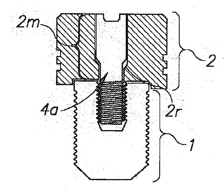
[0023]Alternatively, the surgical jig described above may incorporate a drilling platform which allows for the securing of multiple drill guide assemblies and the subsequent preparation of multiple implant bone preparations and or the insertion and securing of multiple implants into said multiple implant bone preparations or alternatively their insertion and securing in multiple natural extraction sockets that remain after the prior extraction of these teeth.
[0030]Although the apparatus and methods described herein may be employed with the implants described herein, it will be appreciated that they may find utility for securing other implants, and particularly for securing dental implants.
[0031]The methods, apparatus, and implants, may find particular utility for implanting an implant in a bone having a cavity, such as a cavity from a missing tooth, without first re-growing bone in the region of the cavity. As such, a tooth may be extracted and an implant secured to a bone during the same procedure (e.g., with minimal or no bone preparation in order to allow for the insertion of the implant in to the extraction socket(s)), or shortly thereafter (e.g., within one, four, or 20 hours, within one three or five days, or within one, two, three, or four weeks). It will be appreciated that longer periods of time may be encountered between formation of the cavity (e.g., of a missing tooth) and the securing of the implant. The various aspects of the invention allow for increased flexibility in the timing of the securing of an implant.

Problems solved by technology

There are several major drawbacks to this standard implant design.
These drawbacks are derived from the fact that the standard implant design form is actually in very significant variance to the natural structural form of the roots of human teeth.
This major discrepancy in the contour or emergence profile, as it is termed in dentistry, of the crown that is fixed upon the implant abutment (which of necessity must fit precisely into the head portion of the implant) in relation to the gums (as compared to the emergence profile of the natural crown of a tooth as it emerges from the natural root trunk of the tooth) results in large gaps or spaces between the implant crown and the teeth on either side of it and prevents the optimal formation of the interdental papilla (gum tissue between the teeth).
These large open areas or gaps allow for food debris, plaque, and pathogenic bacteria to accumulate between the implant crown and the natural teeth adjacent to it, making these areas very difficult for the patient to keep clean and requiring the patient to use special cleaning implements to try and maintain them free of food debris and plaque.
In many cases this situation over the long-term results in poor health of the gums, causing periodontal (gum) disease of adjacent teeth as well as documented cases of implant failure due to crestal bone resorbtion.
This means that the target bone site for a dental implant is very limited and requires the practitioner who wishes to place dental implants to have acquired a high degree of skill level and clinical experience.
However, until the present teachings, there has been a reluctance to pursue such an approach because of the limited implant designs available to the surgeon.
This is a significant drawback in the structural design of both these applications for the following reasons: As noted above, there are significant limitations on the maximum interdental (mesio-distal distance between the teeth) and bucco-lingual (width of the jawbone) dimensions of the implant site.
The diameter of the “head component” that can typically be accommodated in this limited implant site for missing molar teeth without puncturing this three-dimensional volume of the bone in both of the above two dimensions is itself quite limited.
Both applications described above do not allow for the tight securing to each other of their head component and their root screw component at the time of initial insertion of these implant components into the fresh osteotomy of the jawbones (initial implantation).
This is a significant drawback as it allows for potential micro-infiltration of pathogenic bacteria (at the time of initial implant surgery when the jawbone is directly exposed to the bacteria-laden oral environment as well as during the early stages of healing of the fresh osteotomy) into the micro-gaps between these unsecured endosseous (in bone) implant components and the creation of a reservoir of these pathogenic bone-resorbing bacteria between them.
Additionally, as these endosseous (in the bone) implant components (the head and root screw components) are not tightly secured to each other, these components are free to shift their positions relative to each other during the several months that is required for the bone remodeling that occurs as part of the natural healing process of the osteotomy (implant preparation in the jawbone), another major drawback.

Method used


Image

  • System, apparatus and method for implementing implants
  • System, apparatus and method for implementing implants
  • System, apparatus and method for implementing implants

Examples


Embodiment Construction

[0116]The following description is presented to enable one of ordinary skill in the art to make and use the teachings herein as provided in the context of a particular application and its requirements. Various modifications to the described aspects of the invention (including components, arrangement of components, apparatus, and methods) will be apparent to those with skill in the art, and the general principles defined herein may be applied to other aspects. Therefore, the present teachings are not intended to be limited to the particular aspects shown and described, but are to be accorded the widest scope consistent with the principles and novel features herein disclosed. In other instances, well known methods, procedures, and components have not been described in detail so as not to obscure the present teachings.

[0117]In general, the teachings contemplate systems, means and methods for the preparation and insertion of improved anatomically corrected implants that more closely imi...


PUM


Abstract

Systems, apparatuses, devices, kits and processes are provided to enhance bone implants. The bone implant includes one or more bone attachment components for securing the implant into a bone and a head component independent of and separable from the bone attachment components. In one embodiment, each bone attachment component includes an internally threaded bore hole sleeve for receiving a connector component. The head component preferably is adapted so as to be secured to the one or more bone attachment components at the time of initial implantation of the one or more bone attachment components and the head component into the bone. The head component preferably is adapted to be oriented relative to at least one of the one or more bone attachment components at a predetermined tilt angle, so that the implant generally conforms with a natural root structure of a missing tooth.

Description

CLAIM OF BENEFIT OF FILING DATE[0001]This application claims the benefit of the filing date of U.S. Provisional Patent Application Ser. No. 61 / 438,681, filed 2 Feb. 2011, entitled “A SURGICAL GUIDANCE, DELIVERY SYSTEM AND METHOD FOR IMPLEMENTING IMPLANTS”, which is incorporated herein by reference in its entirety for all purposes.FIELD OF THE INVENTION[0002]The present invention relates generally to bone implants, apparatus for implanting a bone implant, and methods for securing an implant to a bone. The bone implant may be an improved dental implant. The apparatus and method may be employed for preparing a bone and / or securing a dental implant into a bone, such as for a dental prosthesis for one or missing teeth.BACKGROUND OF THE INVENTION[0003]A dental implant is an artificial prosthesis normally comprised of a single cylindrical component to replace the missing root structure of a natural tooth that has been lost. This single stage is inserted into a prepared hollowed out bone pr...

Claims


Application Information

Patent Timeline
Patent Type & Authority Applications(United States)
IPC IPC(8): A61C8/00
CPCA61C8/0068A61C8/0022A61C1/084A61C8/0043A61C8/0087A61C8/0089A61C8/0053A61C8/0066A61C8/008
Inventor SANDERS, DANIEL
Owner MID
Why Eureka
Try Eureka