Hydraulic shock absorber

a technology of shock absorber and shock absorber, which is applied in the direction of shock absorber, liquid based damper, spring/damper, etc., can solve the problems of troublesome parts handling and likely decline in work efficiency, and achieve the effect of simplifying the assembly process

Active Publication Date: 2013-11-28
HITACHI ASTEMO LTD
View PDF11 Cites 29 Cited by
  • Summary
  • Abstract
  • Description
  • Claims
  • Application Information

AI Technical Summary

Benefits of technology

[0007]The present invention has been made in order to solve such problems, and an object thereof is to provide a hydraulic shock absorber in which a cylinder a

Problems solved by technology

However, since the cylinder and the outer cylinder body are elongated parts, there is a problem with an operation of further overlaying the outer cylinder body from the outside to the valve structure to which the cylinder has already been mounted in that handling of the

Method used


Image

  • Hydraulic shock absorber
  • Hydraulic shock absorber
  • Hydraulic shock absorber

Examples


first embodiment

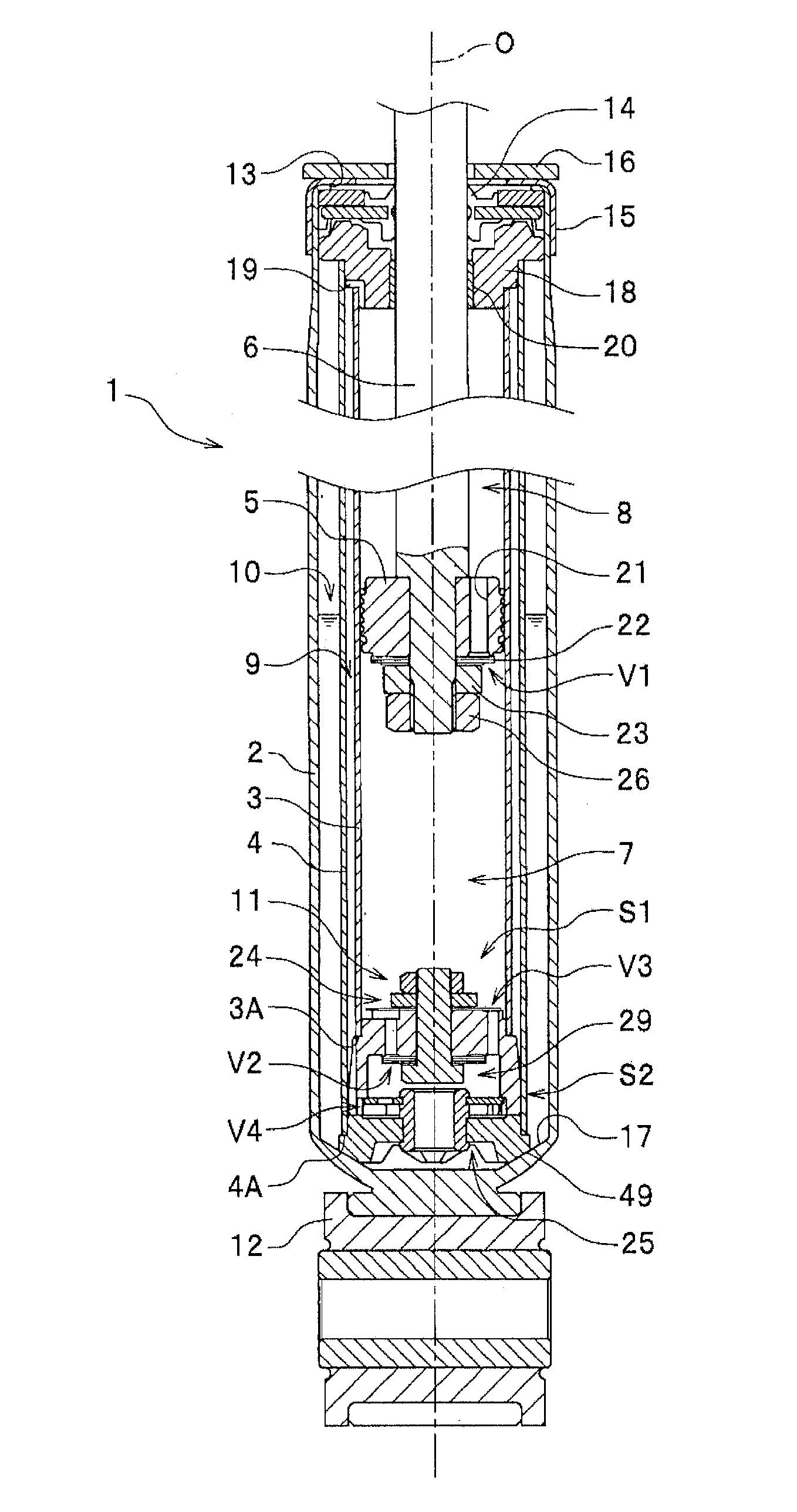
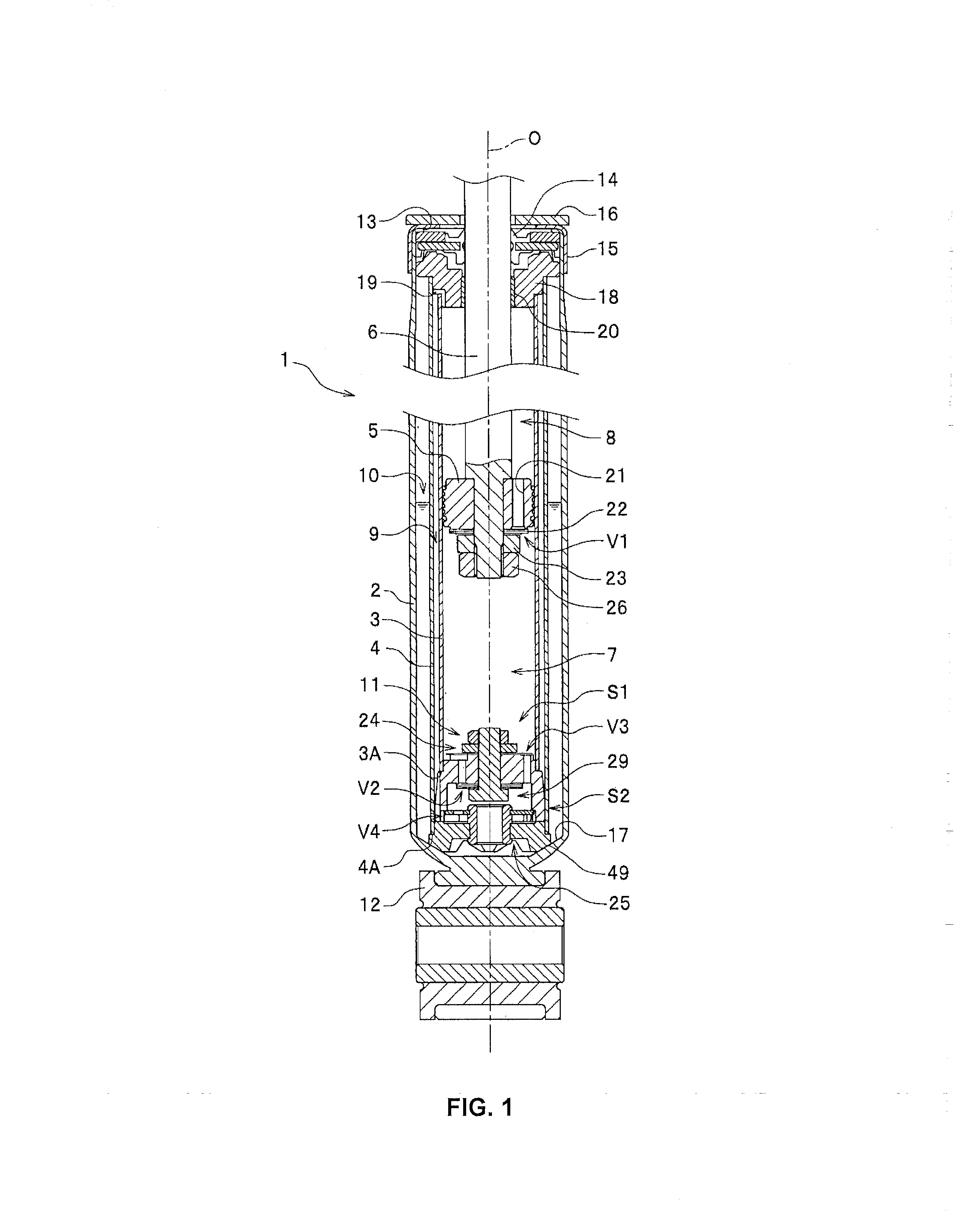
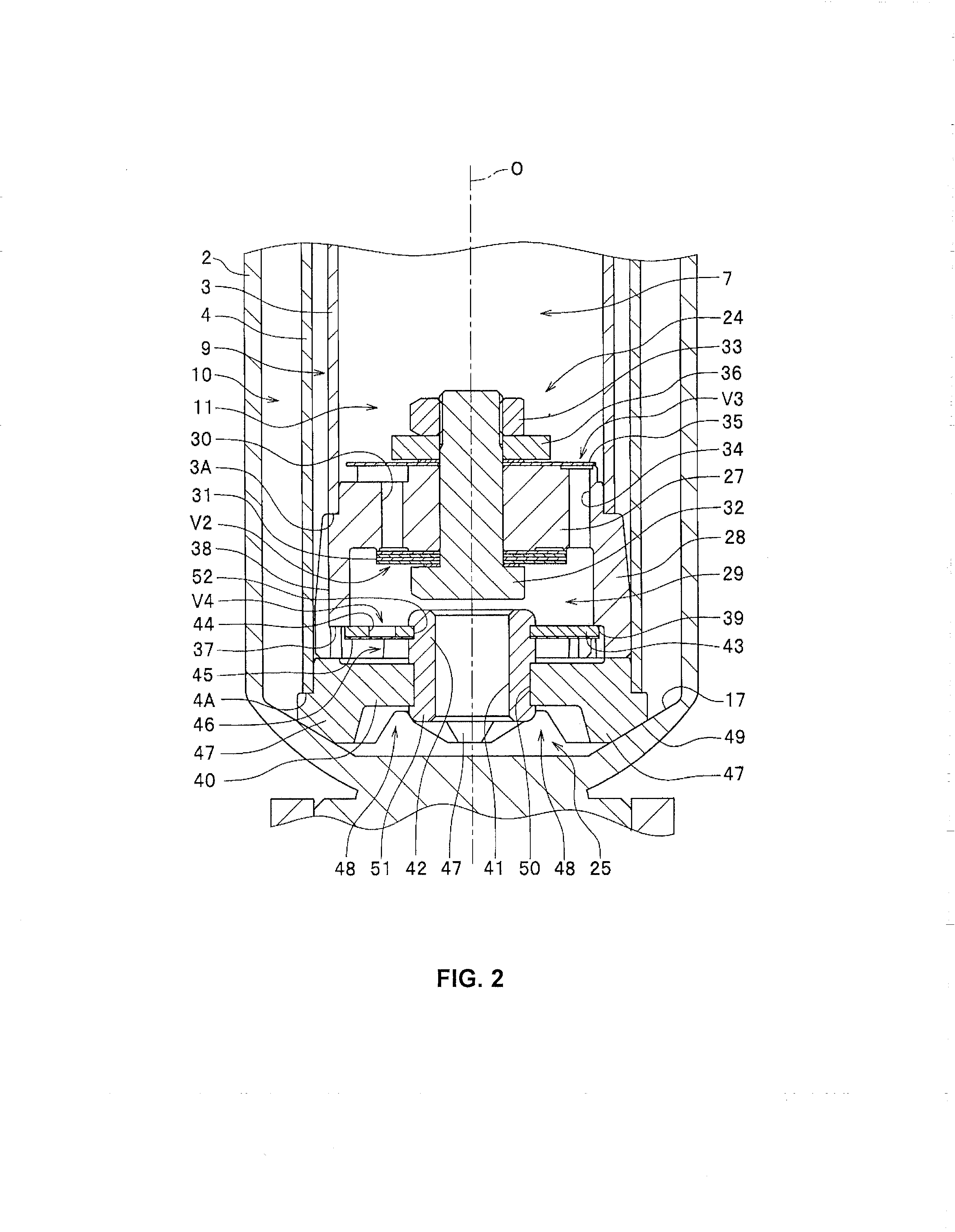
[0033]In FIG. 1, a hydraulic shock absorber 1 includes: a cylindrical damper case 2; a cylinder 3 which is concentrically arranged with the damper case 2 in the damper case 2 and which demarcates a piston oil chamber 7 and a rod oil chamber 8 so as to sandwich a piston 5; an outer cylinder body 4 which is concentrically arranged with the damper case 2 outside the cylinder 3 in the damper case 2, which demarcates between the cylinder 3 and the outer cylinder body 4 a reflux path 9 that connects the piston oil chamber 7 and the rod oil chamber 8 with each other, and which demarcates between the damper case 2 and the outer cylinder body 4 a reservoir chamber 10 that compensates for oil corresponding to tension and compression of a piston rod 6; and a valve structure 11 which is mounted to respective open ends 3A and 4A of the cylinder 3 and the outer cylinder body 4 on the side of the piston oil chamber 7 and which is provided with a valve for controlling a flow of oil between the pist...

second embodiment

[0067]A second embodiment will now be described with reference to FIGS. 5 and 6. In the present embodiment, components similar to those of the first embodiment will be denoted by similar reference numerals and a description thereof will be omitted.

[0068]The second embodiment differs from the first embodiment in a component structure of the second valve structure 25. Compared to the first embodiment adopting three members manufactured independent of each other as the base portion 40, the cylindrical protruding portion 42, and the cylinder supporting plate portion 43, the base portion 40 and the cylindrical protruding portion 42 are constituted by an integrally-molded member in the second embodiment.

[0069]The cylindrical protruding portion 42 has a middle-diameter portion 53 and a small-diameter portion 54 formed above the middle-diameter portion 53, and an engaging flange portion 55 having a diameter larger than that of the small-diameter portion 54 is formed above the small-diameter...

third embodiment

[0072]A third embodiment will now be described with reference to FIGS. 7 and 8. In the present embodiment, components similar to those of the first embodiment will be denoted by similar reference numerals and a description thereof will be omitted.

[0073]The third embodiment similarly differs from the first embodiment in a component structure of the second valve structure 25. Compared to the first embodiment adopting three members manufactured independent of each other as the base portion 40, the cylindrical protruding portion 42, and the cylinder supporting plate portion 43, the cylindrical protruding portion 42 and the cylinder supporting plate portion 43 are constituted by an integrally-molded member in the third embodiment.

[0074]A cylindrical shaft 51 constituting the cylindrical protruding portion 42 is inserted into a through hole 50 of the base portion 40 and a lower end of the cylindrical shaft 51 is fixed to a lower surface of the base portion 40 by riveting or the like. A su...


PUM


Abstract

A hydraulic shock absorber includes: a cylinder which demarcates a piston oil chamber and a rod oil chamber; an outer cylinder body which demarcates between the cylinder and the outer cylinder body a reflux path that connects the piston oil chamber and the rod oil chamber with each other and which demarcates between a damper case and the outer cylinder body a reservoir chamber; and a valve structure mounted to the cylinder and the outer cylinder body. The valve structure has a valve for controlling an oil flow between the piston oil chamber and the reflux path and between the piston oil chamber and the reservoir chamber. The valve structure comprises a first valve structure mounted to an open end of the cylinder and a second valve structure mounted to an open end of the outer cylinder body. A cylinder assembly and an outer cylinder assembly are independently arranged.

Description

CROSS-REFERENCE TO RELATED PATENT APPLICATIONS[0001]This application claims the benefit of Japanese Patent Application No. 2012-117192, filed May 23, 2012, which is incorporated by reference herein.FIELD OF THE INVENTION[0002]The present invention relates to a hydraulic shock absorber.BACKGROUND OF THE INVENTION[0003]Japanese Patent Application Laid-open No. 2012-26564 describes one conventional example of a hydraulic shock absorber which includes, inside a cylindrical damper case: a cylinder which demarcates a piston oil chamber and a rod oil chamber so as to sandwich a piston; an outer cylinder body which is arranged outside the cylinder, which demarcates between the cylinder and the outer cylinder body a reflux path that connects the piston oil chamber and the rod oil chamber with each other, and which demarcates between the damper case and the outer cylinder body a reservoir chamber that compensates for oil corresponding to tension and compression of a piston rod; and a valve st...

Claims


Application Information

Patent Timeline
IPC IPC(8): F16F9/19
CPCF16F9/19F16F9/348F16F9/185
Inventor TSUKAHARA, TAKASHIMANEYAMA, NORIAKI
Owner HITACHI ASTEMO LTD
Why Eureka
Try Eureka