
Method and Apparatus for Adjustably Treating a Sour Gas

a technology of sour gas and adjustment mechanism, which is applied in the direction of hydrogen separation using solid contact, combustible gas purification/modification, separation process, etc., can solve the problems of not practicable or permissible to store hsub>2/sub>, high cost and significant power consumption, and varying process complexity and operational cos

Inactive Publication Date: 2013-11-28
AIR PROD & CHEM INC
View PDF2 Cites 14 Cited by
  • Summary
  • Abstract
  • Description
  • Claims
  • Application Information

AI Technical Summary

Benefits of technology

This approach reduces unnecessary H2S removal and associated costs while ensuring compliance with emissions and purity specifications, even with varying H2S concentrations, thereby optimizing economic and environmental performance.

Problems solved by technology

Equally, it may not be practical or permissible to store the H2S with the CO2.
However, a disadvantage of such AGR processes is that they are both costly and have significant power consumption.
Typically, these are catalyst-based processes that can be of the regenerable type or the ‘once-and-done’ scavenging type and require a varying degree of process complexity and operational cost depending on the processing conditions of the gas being treated.
However, market conditions could limit the economic viability of such a sulfur disposition pathway, as the acid produced from such a process may be unsalable or of sufficiently poor quality that costly neutralization and disposal may be required.
Industries must strike a delicate balance when selecting technologies for processing sour feeds.
This becomes an even more complex problem when one considers that the amount of H2S in the sour gas stream can vary depending on feedstock variations, and variations in the process used to produce and / or separate out the sour gas.
Significant variation in the amount of H2S may, in turn, lead to the H2S removal process becoming economically disadvantageous and / or to product purity and / or emission standards being compromised.

Method used


Image

  • Method and Apparatus for Adjustably Treating a Sour Gas
  • Method and Apparatus for Adjustably Treating a Sour Gas
  • Method and Apparatus for Adjustably Treating a Sour Gas

Examples


Embodiment Construction

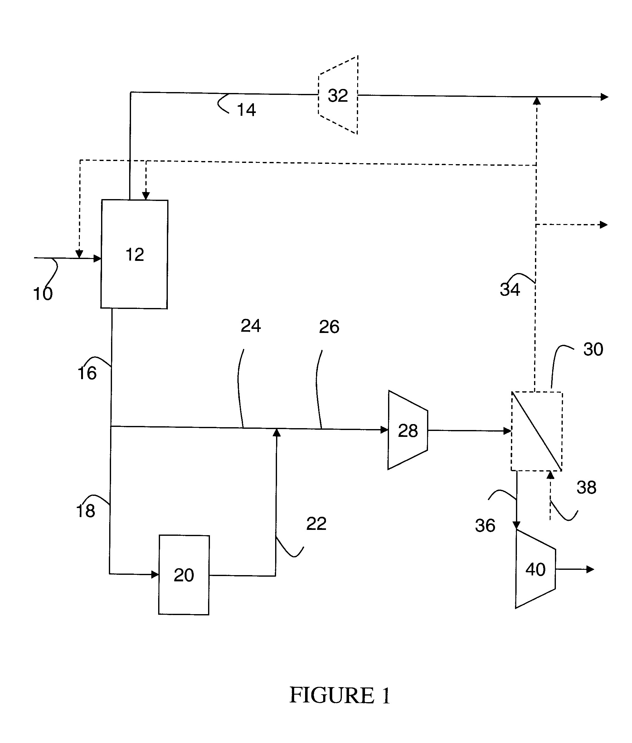
[0040]The present invention provides a method and apparatus for treating a feed gas, comprising CO2, H2S and H2, to produce an H2-enriched product and an H2S-lean, CO2 product. The method comprises:

[0041]separating the feed gas to form a stream of H2-enriched product gas and a stream of sour gas, the sour gas also comprising CO2, H2S and H2 but being depleted in H2 and enriched in H2S and CO2 relative to the feed gas;

[0042]dividing the stream of sour gas into two parts;

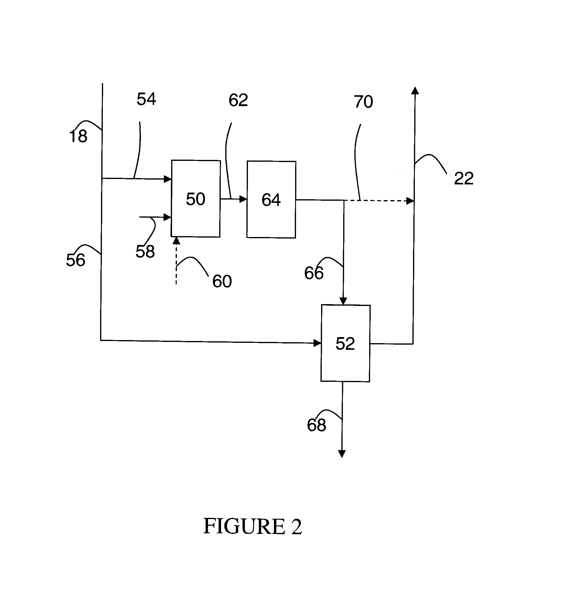
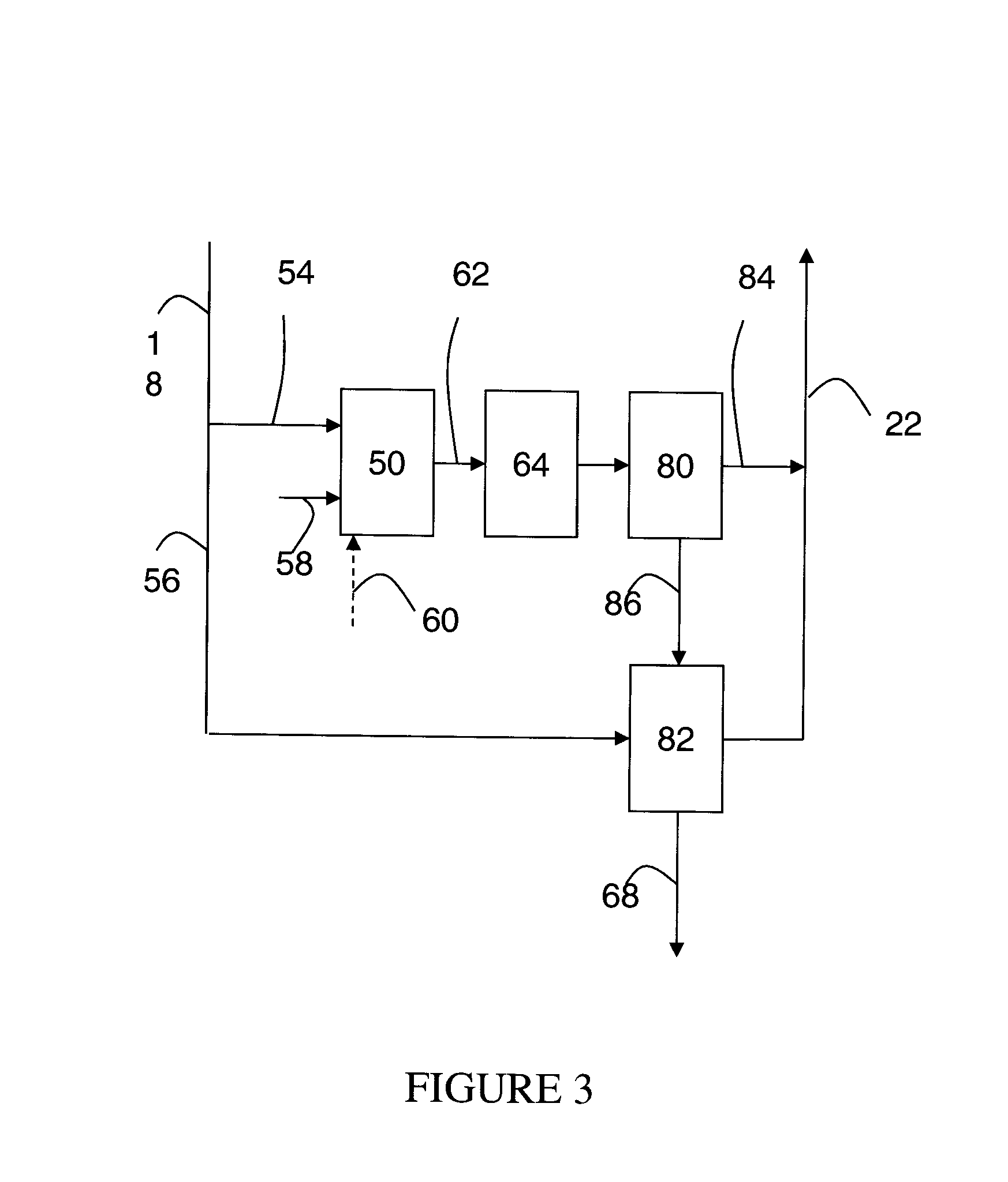
[0043]processing one part of said stream of sour gas in an H2S removal system to form one or more streams of sweetened gas, depleted in H2S and enriched in CO2 relative to the feed gas;

[0044]bypassing the H2S removal system with the other part of said stream of sour gas; and

[0045]combining said stream(s) of sweetened gas with said sour gas bypassing the H2S removal system to form a stream of H2S-lean, CO2 product gas;

[0046]wherein the division of the sour gas between being sent to and processed in the H2S removal syst...


PUM

PropertyMeasurementUnit
molar ratioaaaaaaaaaa
concentrationsaaaaaaaaaa
mole ratioaaaaaaaaaa

Abstract

A feed gas comprising CO2, H2S and H2 is treated to produce an H2-enriched product and an H2S-lean, CO2 product. The feed gas is separated to provide the H2-enriched product and a stream of sour gas. The stream of sour gas is divided into two parts, one of which is processed in an H2S removal system to form one or more streams of sweetened gas, and the other of which bypasses the H2S removal system, the stream(s) of sweetened gas and the sour gas bypassing the H2S removal system then being recombined to form the H2S-lean, CO2 product gas. The division of the sour gas between being sent to and bypassing the H2S removal system is adjusted responsive to changes in the H2S content of the sour gas, so as to dampen or cancel the effects of said changes on the H2S content of the H2S-lean, CO2 product gas.

Description

CROSS-REFERENCE TO RELATED APPLICATIONS[0001]This is a divisional of application Ser. No. 12 / 844,000 filed on Jul. 27, 2010, which is incorporated herein by reference in its entirety.BACKGROUND OF THE INVENTION[0002]The present invention relates to methods and apparatus for separating a feed gas, comprising carbon dioxide (CO2), hydrogen sulfide (H2S) and hydrogen (H2), to form an H2-enriched product gas and a sour gas depleted in H2 and enriched in CO2 and H2S relative to the feed gas, and for adjustably treating said sour gas to produce an H2S-lean, CO2 product gas. The invention has particular application to the separation and treatment of sour syngas mixtures obtained from the gasification or reformation of carbonaceous feedstock.[0003]The production of syngas via reforming or gasifying carbonaceous feedstock is well known. Where the feedstock contains sulfur, such as is often the case for solid (e.g. coal, petcoke) or heavy liquid (e.g. asphaltene) feedstocks for gasification, ...

Claims


Application Information

Patent Timeline
Patent Type & Authority Applications(United States)
IPC IPC(8): C10K1/00C01B32/50
CPCC10K1/004B01D53/047B01D2256/16B01D2257/304B01D2257/504C01B3/501C01B3/506C01B3/56C01B3/58C01B2203/0405C01B2203/043C01B2203/045C01B2203/046C01B2203/0475C01B2203/0485Y02C20/40Y02P20/151
Inventor SCHAFFER, CHARLES LINFORDWRIGHT, ANDREW DAVIDFOGASH, KEVIN BOYLEKLOOSTERMAN, JEFFREY WILLIAMHUFTON, JEFFREY RAYMOND
Owner AIR PROD & CHEM INC
Learn More