Structure having nanoantenna and method for manufacturing same
a nanoantenna and nanotechnology, applied in waveguide devices, drug compositions, other medical devices, etc., can solve problems such as risky application on a macroscopic scal
- Summary
- Abstract
- Description
- Claims
- Application Information
AI Technical Summary
Problems solved by technology
Method used
Image
Examples
example 1
[0113](1) Fabrication or Preparation of Porous Micro-Container
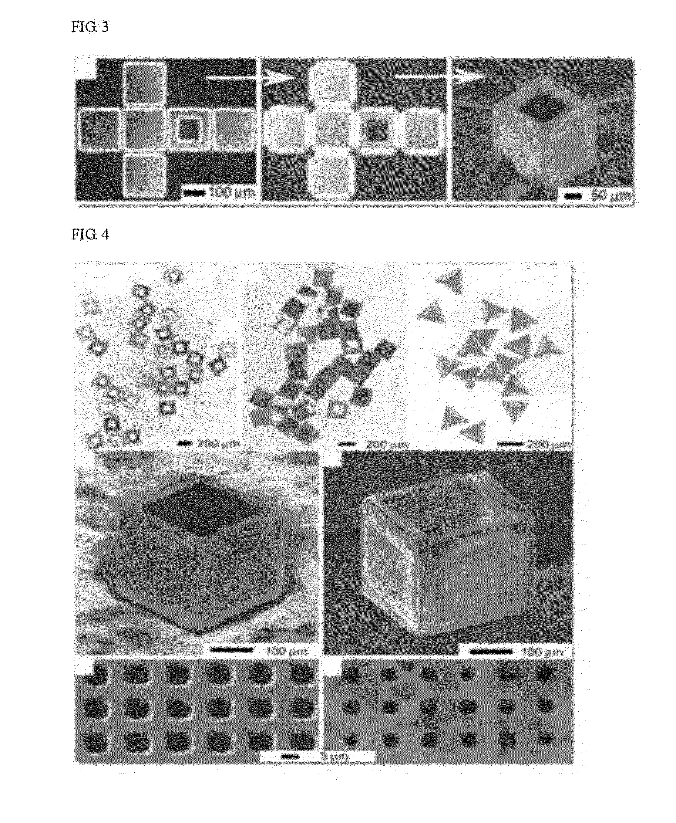
[0114]A two-dimensional Ni basic framework having an average diameter of 50 μm in a planar cross shape was fabricated using a photolithography process, as shown in FIG. 3(a). Next, as shown in FIG. 3(b), a solder hinge was attached to all of the edges of the Ni basic framework. Next, the Ni basic framework having the solder hinge attached thereto was heated at a temperature of 100° C. for 3 minutes, and to a temperature of 250° C. for 3 minutes to liquefy the solder, and a porous micro-container was self-assembled using surface tension of the liquefied solder, as shown in FIG. 3(c). The volume of the porous micro-container was 64,000,000 μm3.
[0115](2) Formation of Dielectric Layer on Porous Micro-Container
[0116]A dielectric layer was formed by coating silicon oxide having a thickness of 200 nm on an outer surface of the prepared porous micro-container using a plasma enhanced chemical vapor deposition (PECVD) process.
[0117...
experimental example 1
[0121]In order to confirm radio frequency characteristics of the structure fabricated in Example 1, High Frequency Structure Simulator (HFSS, Anson Corp.), which is a high frequency electromagnetic simulator, was used.
[0122]FIG. 7 is a graph showing a reflection mode S11 of the structure, which is measured using the HFSS. The reflection mode was analyzed using microwaves having a frequency of 100 MHz to 14 GHz. As shown in FIG. 7, the nanoantenna pattern of Example 1 shows a resonance frequency of 10.8 GHz, and a return loss of −10 dB within a frequency range of 7.5 GHz to 13.4 GHz. A bandwidth of the nanoantenna pattern is 49.3% with a center frequency of 10.8 GHz, when compared to the frequency range of 7.5 GHz to 13.4 GHz.
[0123]FIG. 8 is a graph showing S-parameter experimental analysis of a structure in accordance with an embodiment of the present invention, which is measured using a vector network analyzer (VNA, Agilent 8720 ES). The standard experimental setup was carried out ...
PUM
| Property | Measurement | Unit |
|---|---|---|
| Volume | aaaaa | aaaaa |
| Nanoscale particle size | aaaaa | aaaaa |
| Nanoscale particle size | aaaaa | aaaaa |
Abstract
Description
Claims
Application Information
 - R&D
- Intellectual Property
- Life Sciences
- Materials
- Tech Scout
- Unparalleled Data Quality
- Higher Quality Content
- 60% Fewer Hallucinations
Browse by: Latest US Patents, China's latest patents, Technical Efficacy Thesaurus, Application Domain, Technology Topic, Popular Technical Reports.
© 2025 PatSnap. All rights reserved.Legal|Privacy policy|Modern Slavery Act Transparency Statement|Sitemap|About US| Contact US: help@patsnap.com


