Retrieval systems and methods for use thereof

a technology applied in the field of retrieval systems and methods for use thereof, can solve the problems of increasing the risk of injury, so as to improve the ability of the device, improve the flexibility and strength of the devi

Active Publication Date: 2013-11-28
TYCO HEALTHCARE GRP LP
View PDF6 Cites 88 Cited by
  • Summary
  • Abstract
  • Description
  • Claims
  • Application Information

AI Technical Summary

Benefits of technology

[0012]Another variation of the method include securing an obstruction within a vessel of a patient, by providing an interventional vascular device having a wire attached thereto, where the interventional vascular device is configured to remove the obstruction from the vessel; coupling a shaft to the wire of the interventional vascular device, the shaft having a distal portion and a proximal portion and a lumen extending therethrough and having a flexibility to navigate through tortuous anatomy, an eversible cover having a fixed section affixed near an end of the distal portion of the shaft, a free section extending in a proximal direction from the fixed section and a cover wall extending from the fixed section to the free section, where the eversible cover is expandable against a vessel wall, the eversible cover being axially compliant such that when the interventional vascular device retrieval device is positioned through the shaft lumen and moved in a proximal direction against the eversible cover, the friction of the eversible cover against the vessel wall causes the eversible cover to evert over the interventional vascular device allowing for the free section of the cover to be distal to the interventional vascular device; positioning the shaft and eversible cover over the wire of the interventional vascular device prior to insertion into the patient: and advancing the interventional vascular device, shaft and eversible cover into the vessel to the obstruction. The device can also be configured so that the fixed section of the eversible cover comprises a pre-set shape to reduce a force required to even the evertable cover.
[0015]In another variation, the methods can include further withdrawing the shaft from the vessel such that during withdrawal the eversible cover forms a protective barrier over the obstruction to lessen shearing forces caused by the vessel and reduce dislodging portions of the obstruction from the retrieval device.
[0017]In another example, the devices described herein can include medical device retrieval systems for securing an obstruction within a vessel lumen and for use with a catheter configured to be navigated through the vasculature. In one variation, the device comprises an elongated stent comprising a plurality of struts, the stent being collapsible for positioning in the catheter during delivery and having an expanded profile such that when expanded the struts are configured to engage the obstruction; a shaft fixedly attached to the elongated stent and having a flexibility to navigate through tortuous anatomy; a fluid permeable cover having a distal end coupled to a proximal end of the elongated stent a cover wall defining a cavity and extending along the shaft, and a proximal end being moveable relative to the shaft, where the fluid permeable cover is collapsible for positioning in the catheter during delivery and is expandable upon deployment from the catheter such that at least a portion of the fluid permeable cover is expandable; where the fluid permeable cover is axially pliable such that when the device is deployed in the vessel the frictional forces between the vessel and the fluid permeable cover permit proximal movement of the shaft and elongated stent to cause inversion of the fluid permeable cover wall such that the fluid permeable cover wall evens over the elongated stent.
[0022]The stent retrieval can also include at least one of the plurality of filaments that comprise at least two wires twisted together, the elongated stent body further comprising at least one intersection of filaments, where the wires of each filament are interwoven to provide increased outward radial strength of the elongated stent body and such that the wires slide relative to each other as the elongated stent body expands or compresses in diameter to reduce a force required to linearize the elongated stent body.
[0027]As noted herein, the joint-less construction improves the flexibility and strength of the device by eliminating joints, connection points, or other attachment points. In addition, the joint-less construction improves the ability of the device to be delivered through a small microcatheter. As a result, the device and microcatheter are able to access remote regions of the vasculature.
[0029]It should be noted that in some variations of the invention, all or some of the device can be designed to increase their ability to adhere to the obstruction. For example, the wires may be coupled to an energy source (e.g., RF, ultrasonic, or thermal energy) to “weld” to the obstruction. Application of energy to the device can allow the surrounding portion to deform into the obstruction and “embed” within the obstruction. Alternatively, the device can impart a positive charge to the obstruction to partially liquefy the obstruction sufficiently to allow for easier removal. In another variation, a negative charge could be applied to further build thrombus and nest the device for better pulling force. The wires can be made stickier by use of a hydrophilic substance(s), or by chemicals that would generate a chemical bond to the surface of the obstruction. Alternatively, the filaments may reduce the temperature of the obstruction to congeal or adhere to the obstruction.

Problems solved by technology

An inherent risk in such procedures is that mobilizing or otherwise disturbing the obstruction can potentially create further harm if the obstruction or a fragment thereof dislodges from the retrieval device.
If a particle or the obstruction breaks free from the device and flows downstream, it is highly likely that the particle or obstruction will become trapped in smaller and more tortuous anatomy.
In many cases, the physician will no longer be able to use the same retrieval device to again remove the obstruction because the size of the device may prevent advancing the device to the site of the new obstruction.
These forces have the potential of breaking portions or fragments of the obstruction away.
In some cases, the obstruction can simply break free from the retrieval device and can lodge in a new area causing more concern than the original blockage.
Blockages that interfere with this supply eventually cause the brain tissue to stop functioning.
If the disruption in supply occurs for a sufficient amount of time, the continued lack of nutrients and oxygen causes irreversible cell death (infarction).
Furthermore, a physician might be unaware of one or more fragments that dislodge from the initial obstruction and cause blockage of smaller more distal vessels.
Yet, if attempts at clot dissolution are ineffective or incomplete, the physician can attempt to remove the stent while it is expanded against or enmeshed within the clot.
While this procedure has been shown to be effective in the clinic and easy for the physician to perform, there remain some distinct disadvantages using this approach.
The stent may not sufficiently hold onto the clot as it drags the clot to the cathter.
Another risk is that use of the stent might mobilize the clot might from the original blockage site, but the clot might not adhere to the stent during translation toward the catheter.
This is a particular risk when translating through bifurcations and tortuous anatomy.
If the clot is successfully brought to the guide catheter in the carotid artery, yet another risk is that the clot may be “stripped” or “sheared” from the stent as the stent enters the guide catheter.
Regardless, simply dragging an expanded stent (either fully or partially expanded) can result in undesired trauma to the vessel.
Dragging a fixed metallic (or other) structure can pull the arteries and / or strip the cellular lining from the vessel, causing further trauma such as a hemorrhagic stroke (leakage of blood from a cerebral vessel).
Also, the stent can become lodged on plaque on the vessel walls resulting in further vascular damage.

Method used


Image

  • Retrieval systems and methods for use thereof
  • Retrieval systems and methods for use thereof
  • Retrieval systems and methods for use thereof

Examples


Embodiment Construction

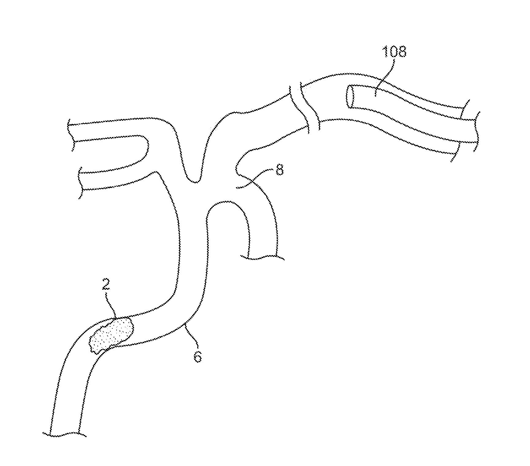
[0055]It is understood that the examples below discuss uses in the cerebral vasculature (namely the arteries). However, unless specifically noted, variations of the device and method are not limited to use in the cerebral vasculature. Instead, the invention may have applicability in various parts of the body. Moreover, the invention may be used in various procedures where the benefits of the method and / or device are desired.

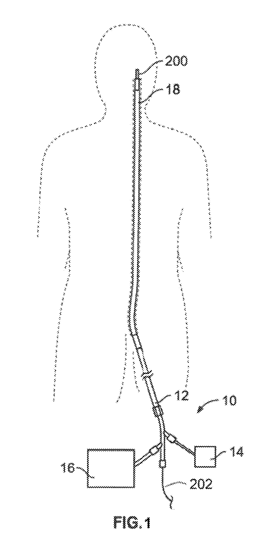
[0056]FIG. 1 illustrates a system 10 for removing obstructions from body lumens as described herein. In the illustrated example, this variation of the system 10 is suited for removal of an obstruction in the cerebral vasculature. As stated herein, the present devices and methods are useful in other regions of the body including the vasculature and other body lumens or organs. For exemplary purposes, the discussion shall focus on uses of these devices and method in the vasculature.

[0057]It is noted that any number of catheters or microcatheters maybe used to locat...


PUM


Abstract

The devices and methods described herein relate to improved structures for removing obstructions from body lumens. Such devices have applicability in through-out the body, including clearing of blockages within the vasculature, by addressing the frictional resistance on the obstruction prior to attempting to translate and / or mobilize the obstruction within the body lumen.

Description

RELATED APPLICATIONS[0001]This application is continuation of PCT Application PCT / US2012 / 039216, publication WO2012 / 162437, filed May 23, 2012 entitled RETRIEVAL SYSTEMS AND METHODS FOR USE THEREOF which is a non-provisional of U.S. Provisional Application Nos. 61 / 489,183 filed May 23, 2011 entitled RETRIEVAL SYSTEMS AND METHODS FOR USE THEREOF, PCT / US2012 / 039216, publication WO2012 / 162437 is also a non-provisional of U.S. Provisional Application No. 61 / 489,254 filed May 24, 2011 entitled STENT RETRIEVER WITH INTEGRATED PROTECTION the entirety of each of which is incorporated by reference.FIELD OF THE INVENTION[0002]The devices described herein are intended to retrieve obstructions from the body. Such devices have applicability throughout the body, including clearing of blockages within body lumens and providing passive protection of such, such as the vasculature, by providing a capturing portion that can translate and / or mobilize the obstruction within the body lumen.BACKGROUND OF ...

Claims


Application Information

Patent Timeline
Patent Type & Authority Applications(United States)
IPC IPC(8): A61F2/06
CPCA61F2/06A61B17/221A61B17/22A61B17/320758A61B2017/22094A61B2017/22084A61B2017/22001A61B2017/22034A61F2/962A61F2/01A61B2017/3435A61F2230/0006A61F2230/0093A61F2/011A61B17/22031A61B17/3207A61F2/95A61B2560/04
Inventor MARTIN, BRIAN B.DIECK, MARTIN S.
Owner TYCO HEALTHCARE GRP LP
Why Eureka
Try Eureka