Storage system and storage control method for using storage area based on secondary storage as cache area

a storage system and control method technology, applied in the field of storage area based on secondary storage as cache area, can solve the problems of limiting the number and occurrence of variations in the number of deletions for each block, and achieve the effect of higher performan

Inactive Publication Date: 2013-11-28
HITACHI LTD
View PDF12 Cites 26 Cited by
  • Summary
  • Abstract
  • Description
  • Claims
  • Application Information

AI Technical Summary

Benefits of technology

[0035]Caching data in a cache area, which is an area based on one part of a secondary storage (for example, at least one of a flash memory device or a disk device) can be carried out effectively inside a single storage system or between different storage systems, thereby making it possible to realize higher performance.

Problems solved by technology

When adopting a system, which fixedly allocates an address for storing data, the rewrite frequency normally differs for each address, resulting in the occurrence of variations in the number of deletions for each block.
There is a limit on the number of times that the respective blocks of a flash memory can be deleted, and it is ordinarily not possible to store data in a block, which has exceeded the limit on the number of deletions.

Method used


Image

  • Storage system and storage control method for using storage area based on secondary storage as cache area
  • Storage system and storage control method for using storage area based on secondary storage as cache area
  • Storage system and storage control method for using storage area based on secondary storage as cache area

Examples


example 1

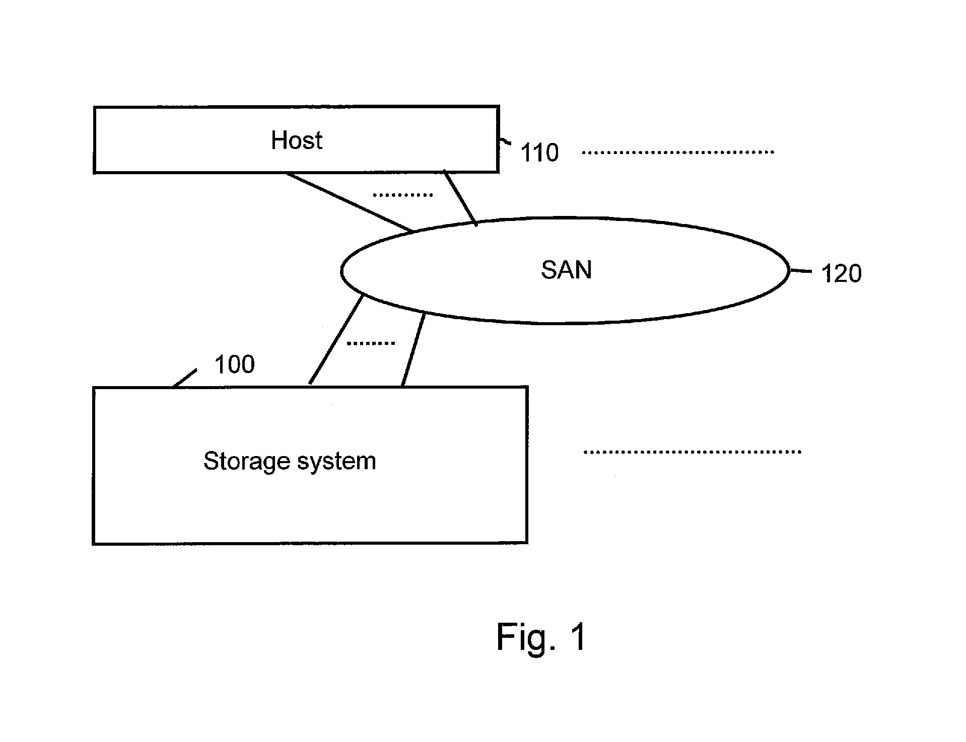
[0079]FIG. 1 shows the configuration of an information system in Example 1.

[0080]The information system comprises a storage system 100 and a host 110, and these are connected, for example, via a communication network such as a SAN (Storage Area Network) 120. The host 110 uses a system for running a user application to read / write required data from / to the storage system 100 via the SAN 120. In the SAN 120, for example, a protocol such as Fibre Channel is used as a protocol enabling the transfer of a SCSI command.

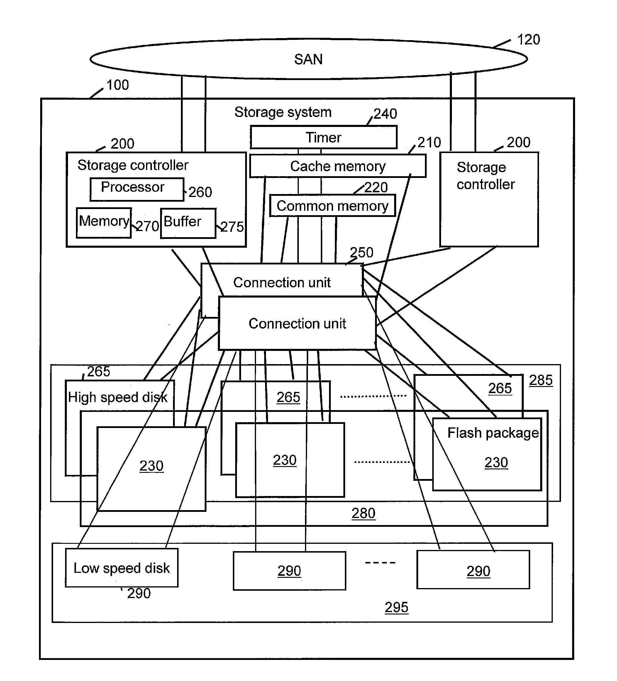
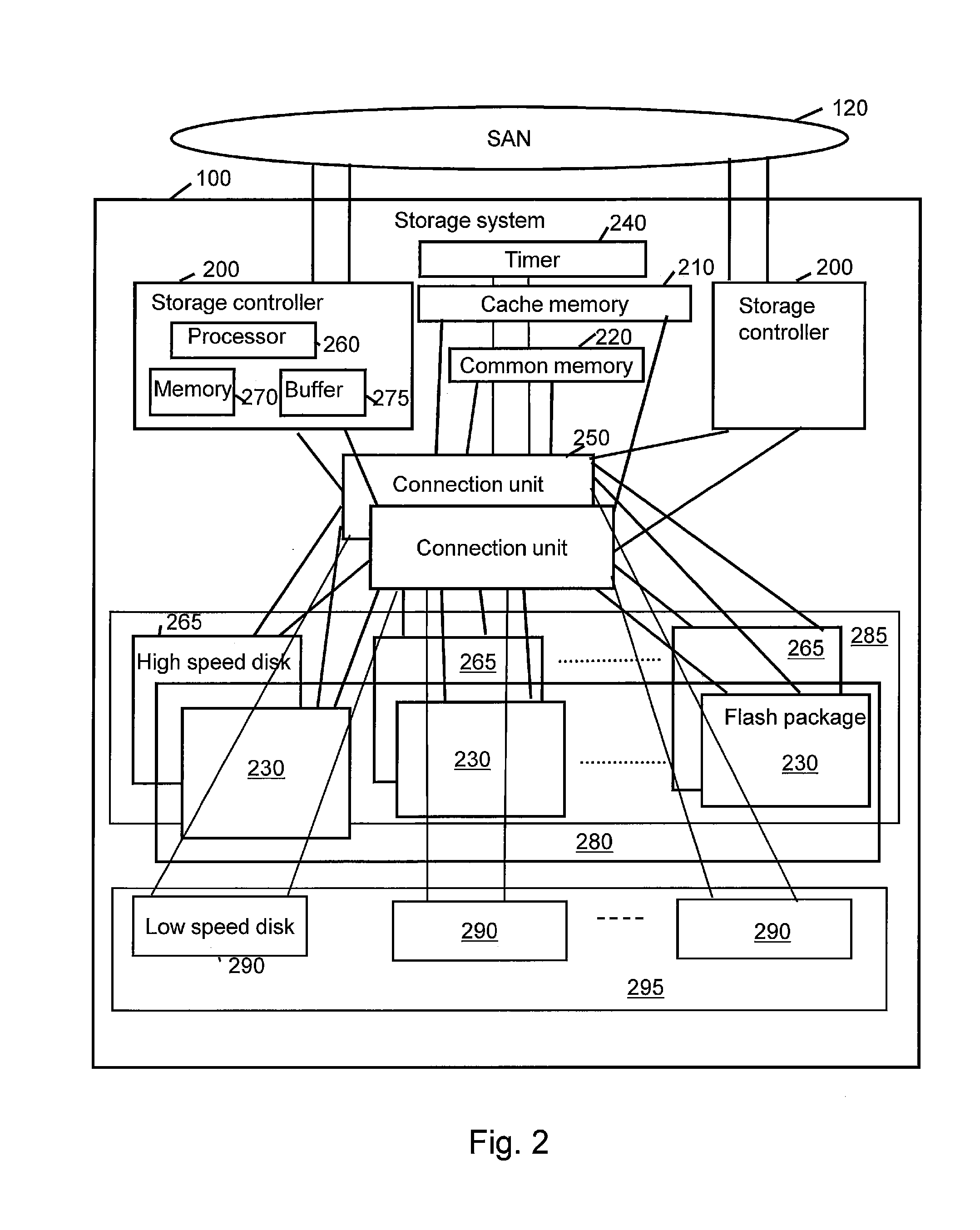
[0081]This example relates to a storage system, which uses a storage area based on a portion of a flash memory device and a portion of a disk device as a cache area, and a control device and a control method for this storage system. In Example 1, the storage system uses a storage area based on a portion of a flash memory device and a portion of a disk device as a cache area for permanently stored data. High performance is achieved in accordance with this. The storage area, wh...

example 2

[0287]Example 2 will be explained below. In so doing, the points of difference with Example 1 will mainly be explained, and explanations of the points in common with Example 1 will either be simplified or omitted.

[0288]FIG. 28 is a block diagram of an information system in Example 2.

[0289]In Example 2, a virtual storage system 150 configured using multiple storage systems 100 exists. In this example, there is one virtual storage system 150, but the present invention is effective even when multiple virtual storage systems 150 exist. It is supposed that the respective storage systems 100 are connected via the SAN 120. In addition, the storage system 100 may also comprise components, which are connected via a WAN 160. In accordance with this, it is supposed that the distance between storage systems 100 becomes fairly long, but that these storage systems 100 are included in a single virtual storage system 150. In this example, it is supposed that all the storage systems 100 comprising t...


PUM


Abstract

In general, a DRAM is used as a cache memory, and when attempting to expand the capacity of the cache memory to increase the hit ratio, the DRAM is required to be physically augmented, which is not a simple task. Consequently, a storage system uses a page, which conforms to a capacity virtualization function (for example, a page allocatable to a logical volume in accordance with Thin Provisioning), as a cache area. This makes it possible to dynamically increase and decrease the cache capacity.

Description

TECHNICAL FIELD[0001]The present invention relates to technology for using a storage area based on a secondary storage as a cache area.BACKGROUND ART[0002]Recent storage systems comprise a myriad of storage functions. There are also storage vendors who provide these storage functions for a fee, and in this regard, increasing the performance of storage functions is considered valuable for storage vendor customers. In addition, the performance of a flash memory device is superior to that of a magnetic disk device or other such disk storage device, and with flash memory prices becoming less expensive recently, flash memory devices are increasingly being mounted in storage systems in place of disk storage devices. A storage system generally comprises a cache memory (for example, a DRAM (Dynamic Random Access Memory)), and frequently accessed data stored in a secondary storage, such as either a flash memory apparatus or a disk storage, is stored in the cache memory.[0003]Due to the chara...

Claims


Application Information

Patent Timeline
Patent Type & Authority Applications(United States)
IPC IPC(8): G06F15/167
CPCG06F12/0871G06F12/0893
Inventor YAMAMOTO, AKIRASAITO, HIDEOEGUCHI, YOSHIAKIYAMAMOTO, MASAYUKIMORISHITA, NOBORU
Owner HITACHI LTD
Why Eureka
Try Eureka