Steel gear and manufacturing method for the same

a manufacturing method and gear technology, applied in heat treatment equipment, furnaces, hoisting equipment, etc., can solve the problems of poor obd taper, steel gear not having sufficient dimensional accuracy, distortion of outer peripheral ring portions, etc., to achieve high dimensional accuracy, increase internal hardness, and high strength

Active Publication Date: 2013-12-05
AISIN AW CO LTD
View PDF12 Cites 5 Cited by
  • Summary
  • Abstract
  • Description
  • Claims
  • Application Information

AI Technical Summary

Benefits of technology

[0030]According to the manufacturing method described above, in addition, the region including the carburized layer and at a depth, in the inward direction from the tooth bottom of the toothed shape on the outer peripheral surface, larger than the depth of the carburized layer is also partially subjected to high-frequency quenching, which increases the internal hardness. Therefore, it is possible to obtain a steel gear having high dimensional accuracy and high strength that is suitable for a high torque transfer gear, such as a differential gear, that is required to provide high dimensional accuracy and that is subjected to a stress applied not only to the surface layer of the toothed shape thereof but also to the inside thereof. In addition, the steel gear, although not subjected to a shot-peening process, can provide strength that is approximately as high as that

Problems solved by technology

In the case where the “carburizing/slow cooling/high-frequency quenching process” according to the related art is simply applied to a steel gear material in which the flange portion is coupled to the inner peripheral surface of the outer peripheral ring portion at a location slightly displaced from the center position of the inner peripheral surface in the axial direction toward one side in the axial direction, however, the outer peripheral ring portion m

Method used


Image

  • Steel gear and manufacturing method for the same
  • Steel gear and manufacturing method for the same
  • Steel gear and manufacturing method for the same

Examples


embodiment

[0076]A steel gear and a manufacturing method for a steel gear according to an embodiment will be specifically described below with reference to the drawings. The steel gear according to the embodiment is obtained by applying the present invention to a differential gear. Reference symbols are used as appropriate.

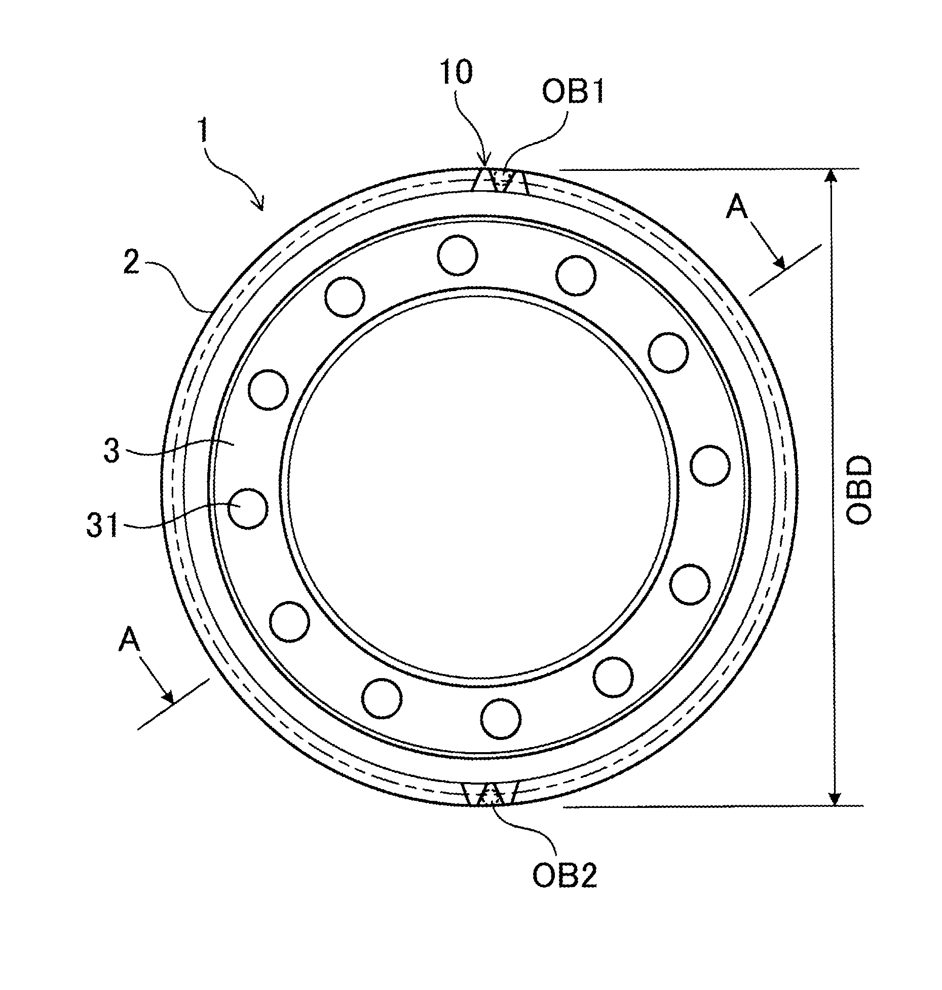
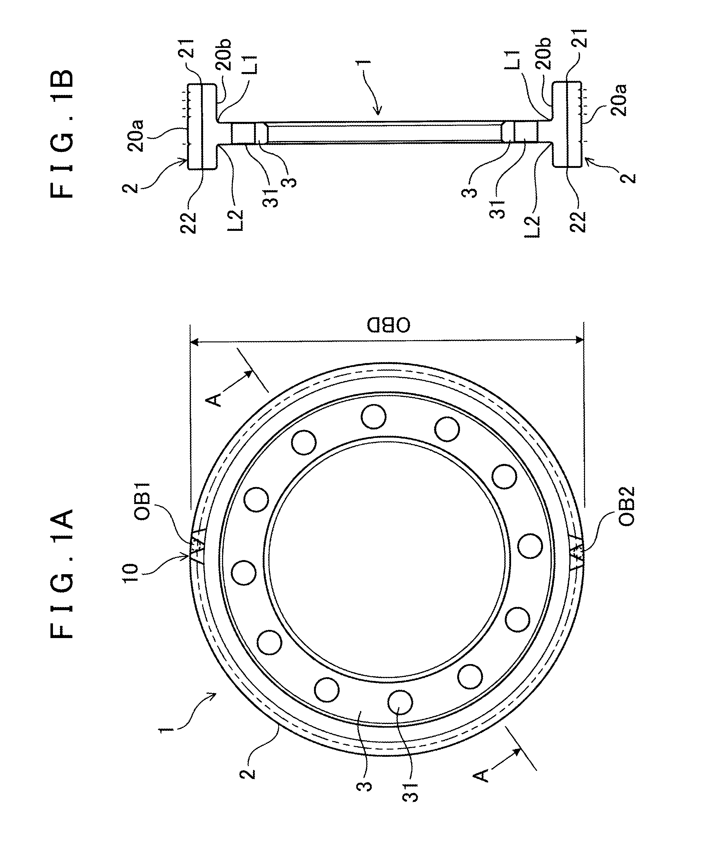
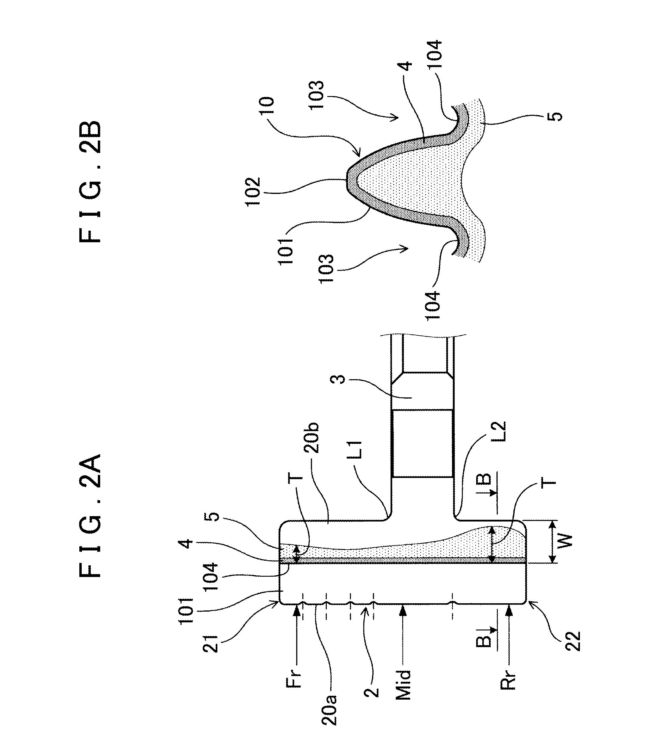
[0077]First, a schematic configuration of a steel gear according to a first embodiment will be described. As shown in FIG. 1, a steel gear 1 includes a generally cylindrical outer peripheral ring portion 2, on an outer peripheral surface 20a of which a toothed shape 10 is formed, and a flange portion 3 provided to extend radially inward from an inner peripheral surface 20b of the outer peripheral ring portion 2. The outer peripheral ring portion 2 includes a first projecting portion 21 that projects toward one side in the axial direction with respect to a coupling position L1 with the flange portion 3, and a second projecting portion 22 that projects toward the other side in...


PUM

PropertyMeasurementUnit
Depthaaaaaaaaaa
Distanceaaaaaaaaaa

Abstract

A steel gear 1 includes a generally cylindrical outer peripheral ring portion 2, on an outer peripheral surface 20a of which a toothed shape 10 is formed, and a flange portion 3 provided to extend radially inward from an inner peripheral surface 20b of the outer peripheral ring portion 2. The outer peripheral ring portion 2 includes a first projecting portion 21 that projects toward one side in the axial direction with respect to a coupling position at which the first projecting portion 21 is coupled to the flange portion 3, and a second projecting portion 22 that projects toward the other side in the axial direction with respect to a coupling position at which the second projecting portion 22 is coupled to the flange portion 3. The axial length of the first projecting portion 21 is longer than the axial length of the second projecting portion 22. The outer peripheral ring portion 2 includes a carburized layer 4 formed in a surface layer of the toothed shape 10, and a thermal history layer 5 formed in a region including the carburized layer 4 and at a depth, in the inward direction from the outer peripheral surface 20a, larger than the depth of the carburized layer 4, the thermal history layer 5 having a history of being heated through high-frequency induction heating until becoming austenite. The depth T of the thermal history layer 5 in the inward direction from a tooth bottom 104 of the toothed shape 10 is larger at the second projecting portion 22 than at the first projecting portion 21.

Description

INCORPORATION BY REFERENCE[0001]The disclosure of Japanese Patent Application No. JP 2011-077747 filed on Mar. 31, 2011 including the specification, drawings and abstract is incorporated herein by reference in its entirety.BACKGROUND OF THE INVENTION[0002]The present invention relates to a steel gear and a manufacturing method for a steel gear.DESCRIPTION OF THE RELATED ART[0003]Conventionally, steel gears are used in many industrial fields. For example, differential devices used in the automotive field have a large number of steel gears. There are various shapes of steel gears. Japanese Patent Application Publication No. 2010-131626 (JP 2010-131626 A) discloses a gear including a cylindrical outer peripheral ring portion, on the outer peripheral surface of which a toothed shape is formed, and a flange portion coupled to the inner peripheral surface of the outer peripheral ring portion at a location slightly displaced from the center position of the inner peripheral surface in the a...

Claims


Application Information

Patent Timeline
IPC IPC(8): F16H55/06C23C8/22C23C8/80
CPCF16H55/06C23C8/80C23C8/22C21D1/10C21D9/32C21D2221/00C22C1/02C22C38/00C22C38/02C22C38/04C22C38/18F16H55/17Y02P10/25Y10T74/1987
Inventor OBAYASHI, KOJITAGUCHI, KEITAMIYAKE, YASUTAKAOGISO, TAKAAKI
Owner AISIN AW CO LTD
Why Eureka
Try Eureka