Production method of multilayer printed wiring board and multilayer printed wiring board

a multi-layer printing and wiring board technology, applied in the direction of printed circuit details, printed circuit manufacturing, printed element electric connection formation, etc., can solve the problems of deteriorating the flow of plating solution, reducing the reliability of insulation, and etching back phenomenon in such via holes, so as to achieve high reliability

Active Publication Date: 2013-12-05
AJINOMOTO CO INC +1
View PDF4 Cites 10 Cited by
  • Summary
  • Abstract
  • Description
  • Claims
  • Application Information

AI Technical Summary

Benefits of technology

[0011]It is another object of the present invention to provide novel processes for making a multilayer printed wiring board which can sufficiently suppress the etch back phenomenon and protrusion of a glass cloth from the wall surface of a via hole, and can form a highly reliable via.
[0013]It is another object of the present invention to provided novel multilayer printed wiring board having a highly reliable via.
[0014]These and other objects, which will become apparent during the following detailed description, have been achieved by the inventors' discovery that, by forming, by laser irradiation, a via hole in an insulating layer formed by thermally curing a prepreg comprised of a glass cloth impregnated with a thermosetting resin composition, etching the glass cloth protruding from the sidewall surface of the via hole, and applying a desmear treatment with an oxidizing agent solution to the via hole, a clearance having an opening on the side wall surface of a via hole, which is formed due to the advanced surface dissolution of the glass cloth during etching thereof, can be eliminated because the oxidizing agent solution etches the resin cured product during the desmear treatment.
[0036]According to the process of making a multilayer printed wiring board of the present invention, since a desmear treatment with an oxidizing agent solution is applied to a via hole formed on the insulating layer, after the etching treatment of a glass cloth protruding from the sidewall surface of the via hole, a clearance having an opening on the sidewall surface of a via hole (clearance due to dissolution of glass cloth), which is possibly formed during the etching treatment of the glass cloth can be eliminated because the oxidizing agent solution etches the resin cured product constituting the insulating layer during the desmear treatment. Accordingly, both etching that sufficiently reduces the length of the protrusion of a glass cloth from the sidewall surface of the via hole and suppression of the etch back phenomenon can be simultaneously achieved, and a highly reliable via free of inconveniences due to a degraded flow of a plating solution (reduced flowability) or etch back phenomenon can be formed. Therefore, the present invention can afford, for example, a highly reliable multilayer printed wiring board having a small diameter via having a top diameter of not more than 75 μm.

Problems solved by technology

This is a phenomenon common to vias formed on insulating layers, which causes inconvenience such as decreased insulation reliability between via 20 and an adjacent via and the like.
However, according to the investigation by the present inventors, it has been found that the problem of a deteriorated flow of a plating solution becomes significant for a via hole with a smaller diameter, for example, a via hole with a small top diameter of not more than 75 μm, and a glass cloth protruding from a via hole wall surface needs to be etched sufficiently, thus causing the etch back phenomenon in such via holes.
In other words, the present inventors have found that sufficient etching of a glass cloth results in etching of the glass cloth inside the wall of a via hole, causing the etch back phenomenon, and etching under the conditions leaving the glass cloth intact inside the wall of a via hole fails to sufficiently etch the glass cloth protruding from the wall surface, thus causing deteriorated flow of a plating solution (low flowability).

Method used


Image

  • Production method of multilayer printed wiring board and multilayer printed wiring board
  • Production method of multilayer printed wiring board and multilayer printed wiring board
  • Production method of multilayer printed wiring board and multilayer printed wiring board

Examples


example 1

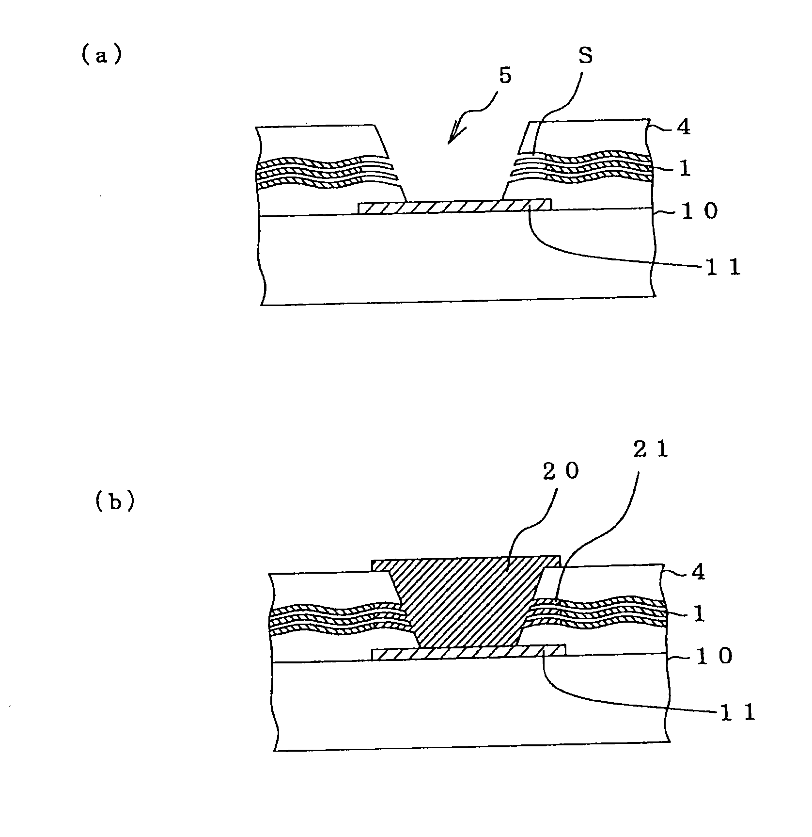
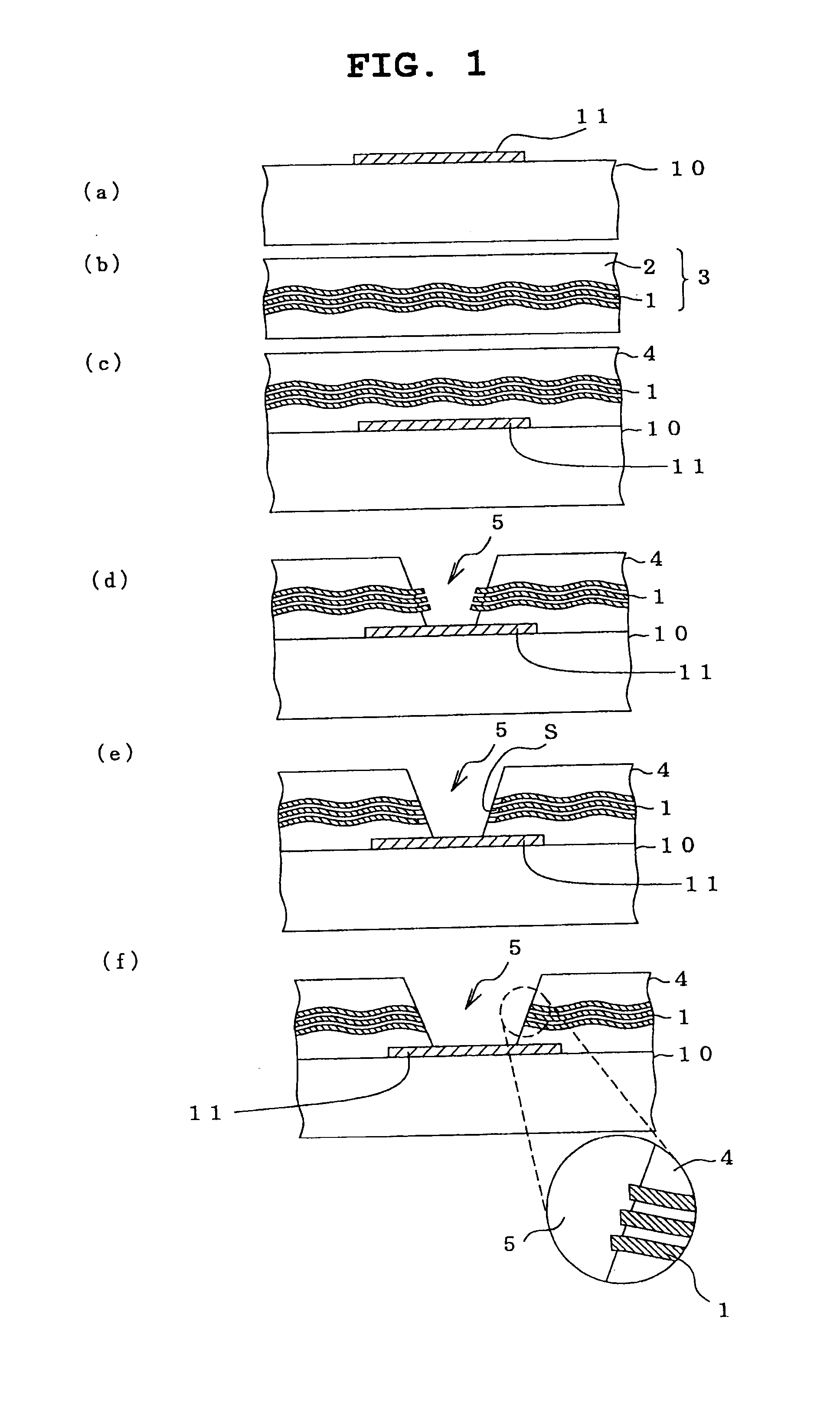
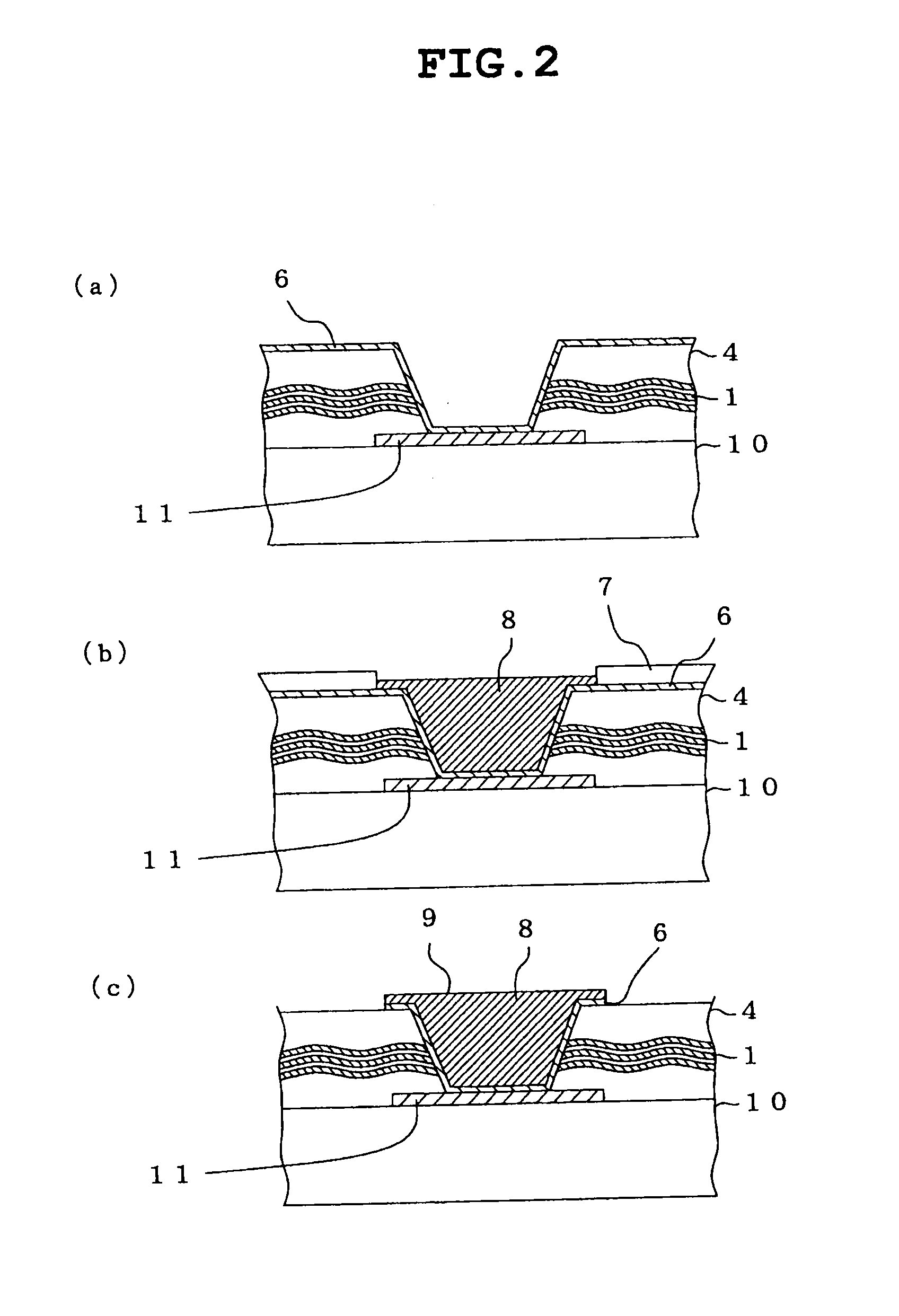
[0092]A protection film-detached prepreg with PET film was laminated on both sides of a copper-clad laminate plate (circuit substrate) having a thickness of 0.2 mm after circuit formation (circuit conductor thickness 18 μm). The PET film was detached, and the laminate was thermally cured to form an insulating layer having a thickness of 32 μm on both surfaces of the above-mentioned circuit substrate. Then, a via hole having a top diameter 60 μm, a bottom diameter 50 μm was formed in the insulating layer laminated on one surface of the circuit substrate by carbon dioxide gas laser.

[0093]The resulting circuit substrate was immersed in an aqueous solution, which was obtained by diluting a glass etching solution (“Enplate MLB GLASS ETCH ADDITIVE” manufactured by Meltex Inc.) containing fluoroboric acid at a concentration of about 50 g / L with ion exchange water to a concentration of 20 mL / L, at 40° C. for 5 minutes for etching of the glass cloth. Then the via hole was subjected to a desm...

example 2

[0100]The operation and measurements in the same manner as in Example 1 were performed except that an aqueous solution obtained by diluting the glass etching solution (“Enplate MLB GLASS ETCH ADDITIVE” manufactured by Meltex Inc.) with ion exchange water to a concentration of 35 mL / L was used. The surface of the insulating layer had an Ra (arithmetic mean roughness) of 800 nm.

example 3

[0101]The operation and measurements in the same manner as in Example 1 were performed except that an aqueous solution obtained by diluting the glass etching solution (“Enplate MLB GLASS ETCH ADDITIVE” manufactured by Meltex Inc.) with ion exchange water to a concentration of 50 mL / L was used. The surface of the insulating layer had an Ra (arithmetic mean roughness) of 800 nm.


PUM

PropertyMeasurementUnit
lengthaaaaaaaaaa
Raaaaaaaaaaa
diameteraaaaaaaaaa

Abstract

Multilayer printed wiring boards may be prepared by forming a via hole by laser irradiation in insulating layer formed by a prepreg, comprised of a glass cloth impregnated with a thermosetting resin composition, and subjecting the via hole to a glass etching treatment with a glass etching solution and then to a desmear treatment with an oxidizing agent solution. By such a process, etch back phenomenon and excessive protrusion of glass cloth from the wall surface of a via hole can be sufficiently suppressed, and a highly reliable via can be formed. Particularly, a highly reliable via can be formed in a small via hole having a top diameter of 75 μm or below.

Description

CROSS REFERENCES TO RELATED APPLICATIONS[0001]This application claims priority to Japanese Patent Application No. 2007-303737, filed on Nov. 22, 2007, which is incorporated herein by reference in its entirety.BACKGROUND OF THE INVENTION[0002]1. Field of the Invention[0003]The present invention relates to processes for making a multilayer printed wiring board. The present invention also relates to multilayer printed wiring boards produced by such a process.[0004]2. Discussion of the Background[0005]As a technique for producing a multilayer printed wiring board, a production method using a build-up process of alternately layering an insulating layer and a conductive layer on a core substrate is conventionally known. For formation of an insulating layer, an adhesive film is exclusively used, which is formed by forming a thermosetting resin layer on a plastic film, where an insulating layer is formed by laminating the adhesive film on an internal-layer circuit substrate, detaching the p...

Claims


Application Information

Patent Timeline
Patent Type & Authority Applications(United States)
IPC IPC(8): H05K3/42H05K1/02H05K3/00H05K3/46
CPCH05K3/42H05K1/02H05K1/0366H05K3/0032H05K3/0035H05K3/0055H05K2203/0796Y10T29/49165Y10T29/49155H05K1/0298H05K3/4038H05K3/4626H05K3/02
Inventor OHASHI, SEIICHIROHAYASHI, EIICHINAKAMURA, SHIGEOYAZAWA, TAKAAKINAKAMURA, JUNICHI
Owner AJINOMOTO CO INC
Why Eureka
Try Eureka