Expanded-beam connector with molded lens

a technology of optical connectors and molded lenses, applied in the direction of optics, instruments, optical light guides, etc., can solve the problems of affecting the optical transmission, and affecting the physical contact between the fiber and the light path of the mating connector, so as to eliminate the process step of polishing the ferrule and eliminate the effect of the ferrul

Active Publication Date: 2013-12-05
TYCO ELECTRONICS LOGISTICS AG (CH)
View PDF36 Cites 17 Cited by
  • Summary
  • Abstract
  • Description
  • Claims
  • Application Information

AI Technical Summary

Benefits of technology

[0012]In one embodiment, the molded lens body is configured to receive the fiber such that no polishing of a ferrule is required. In yet another embodiment, the lens body is configured to receive a buffered fiber, thereby not only eliminating the process step of polishing the ferrule, but also eliminating the ferrule altogether.

Problems solved by technology

Such connectors are used traditionally in high vibration and / or dirty environments, where “physical contact” between the fiber and the light path of mating connector is problematic.
Specifically, in dirty environments, particulates may become trapped between connectors during mating.
Such debris has a profoundly detrimental effect on the optical transmission since the particles are relatively large compared to the optical path (e.g., 10 microns diameter in single mode) and are therefore likely to block at least a portion of the optical transmission.
Furthermore, in high-vibration environments, optical connectors having ferrules in physical contact tend to experience scratching at their interface.
This scratching diminishes the finish of the fiber end face, thereby increasing reflective loss and scattering.
Thus, the glass lens used for a single-mode expanded beam application is different from a multi-mode lens and is typically more expensive.
Regardless of whether the lens is configured for use in a multi-mode or single-mode connector, it is the most expensive component in the connector system.

Method used


Image

  • Expanded-beam connector with molded lens
  • Expanded-beam connector with molded lens
  • Expanded-beam connector with molded lens

Examples


Embodiment Construction

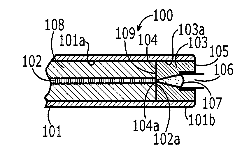
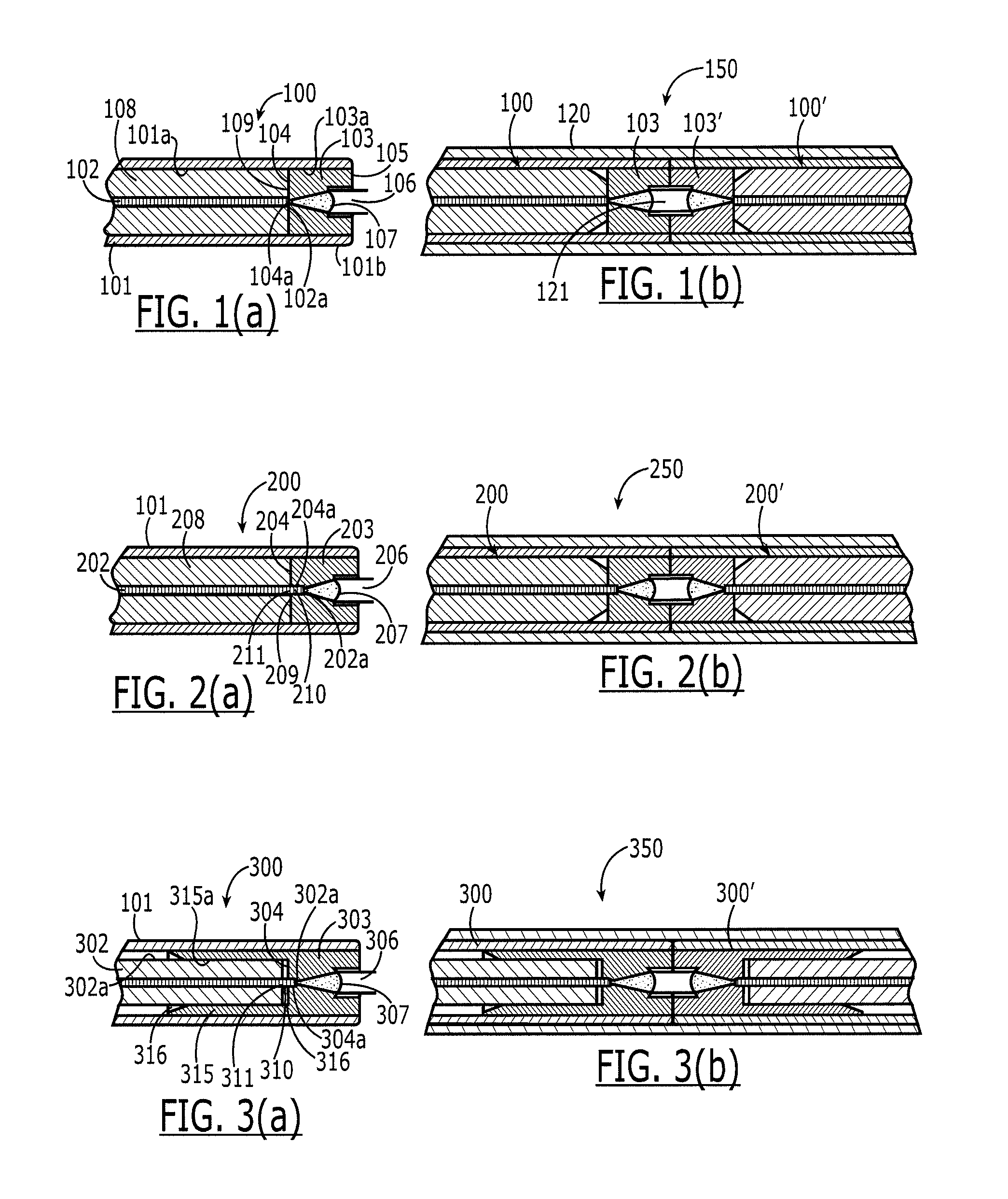
[0019]Referring to FIGS. 1(a) & (b), 2(a) & (b), and 3(a) & (b), various embodiments of the expanded-beam connector 100, 200, 300 of the present invention are shown. In each embodiment, the connector 100, 200, 300 comprises a sleeve 101 for holding at least one fiber 102, 202, 302 having a fiber end face 102a, 202a, 302a. The sleeve 101, which is essentially (although not necessarily) the same for each embodiment, has an interior surface 101a having a certain geometry. The connector 100, 200, 300 also comprises a lens body 103, 203, 303. The lens body 103, 203, 303 is molded with a first face 104, 204, 304 and a second face 105, 205, 305, the first and second faces being substantially planar. The first face has an interface point 104a, 204a, 304a for optically coupling with the fiber end face 102a, 202a, 302a. The second face has at least one lens, which, in this embodiment, is a convex surface 107, 207, 307. The focal point of each convex surface 107, 207, 307 is essentially at the...


PUM


Abstract

An expanded-beam connector comprising a sleeve for holding at least one fiber and one lens body, the sleeve having an interior surface having a certain geometry, a fiber having a fiber end face, and a lens body, the lens body being formed with a first face and a second face, the first and second faces being substantially planar, the first face having an interface point for optically coupling with the fiber end face, the second face having a convex surface, the interface point and the convex surface being optically coupled through the lens body, the lens body having an outer periphery at least a portion of which has the certain geometry such that the lens body is held in a precise radial position relative to the sleeve when disposed in the sleeve.

Description

FIELD OF INVENTION[0001]The present invention relates generally to an expanded-beam optical connector, and, more particularly, to an expanded-beam plug and receptacle termini-type optical connector.BACKGROUND OF INVENTION[0002]Optical fiber connectors are a critical part of essentially all optical fiber communication systems. For instance, such connectors are used to join segments of fiber into longer lengths, to connect fiber to active devices, such as radiation sources, detectors and repeaters, and to connect fiber to passive devices, such as switches, multiplexers, and attenuators. The principal function of an optical fiber connector is to hold the fiber end such that the fiber's core is axially aligned with an optical pathway of the mating structure. This way, light from the fiber is optically coupled to the optical pathway.[0003]Of particular interest herein are “expanded beam” optical connectors. Such connectors are used traditionally in high vibration and / or dirty environment...

Claims


Application Information

Patent Timeline
Patent Type & Authority Applications(United States)
IPC IPC(8): G02B6/32
CPCG02B6/32G02B6/3853G02B6/322G02B6/38G02B6/3817
Inventor GRINDERSLEV, SOREN
Owner TYCO ELECTRONICS LOGISTICS AG (CH)
Why Eureka
Try Eureka