Cap for forming sealed cavity around fastener

a technology of sealing cavity and cap, which is applied in the direction of threaded fasteners, screw heads, manufacturing tools, etc., can solve the problems of increasing the strength of the bond, and achieve the effect of reducing the exposure to damage and minimising the concentration of stress

Active Publication Date: 2013-12-05
AIRBUS OPERATIONS LTD
View PDF8 Cites 21 Cited by
  • Summary
  • Abstract
  • Description
  • Claims
  • Application Information

AI Technical Summary

Benefits of technology

[0025]Preferably the inner and outer cap have a curved domed shape. This reduces exposure to damage (for instance by being kicked by the foot of an installer), minimises stress concentration, and assists in the flow of sealant into the pocket.

Problems solved by technology

It has been found that such a structure is susceptible to failure at the sealant / cap interface, so by increasing the surface area of the sealant / cap interface the strength of the bond is increased.

Method used


Image

  • Cap for forming sealed cavity around fastener
  • Cap for forming sealed cavity around fastener
  • Cap for forming sealed cavity around fastener

Examples


Embodiment Construction

)

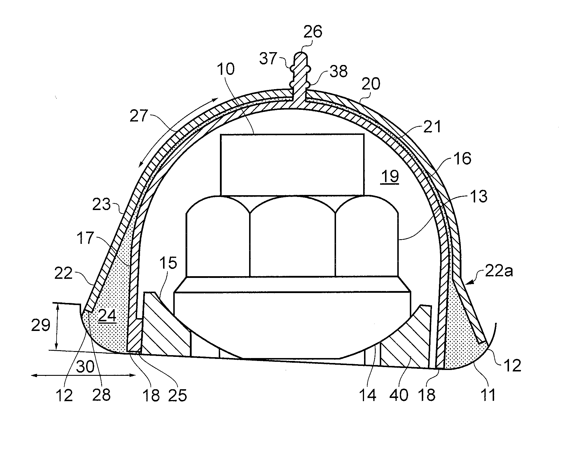
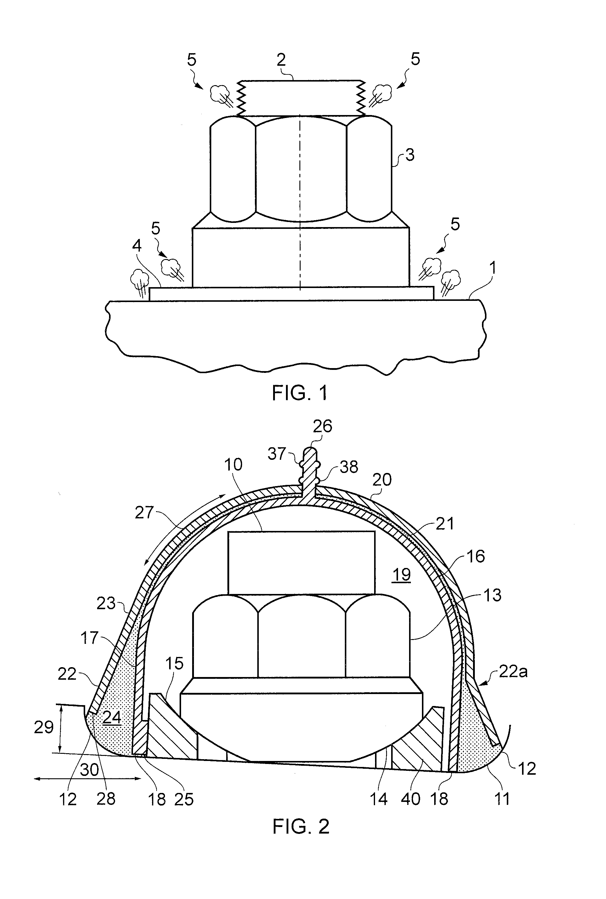
[0038]FIG. 2 is a cross-sectional side view showing a metal bolt 10 passing through a composite panel 11 at an angle of 3° to the plane of the panel 11. The panel has raised features 12 on both sides, which may be for example fillets, ribs or spar caps. An internally threaded metal nut 13 is screwed onto the bolt 10 and has a convex spherical surface 14 which engages a concave spherical surface 15 of a washer 40. The spherical nut and washer enable the fastener to be securely fixed to the panel even though the bolt is not perpendicular to the panel.

[0039]A spark containment cap is fitted over the fastener. The cap has a two-part construction with an outer cap 20 fit onto an inner cap 16 so that the inner cap 16 is nested within the outer cap 20. The caps 16, 20 have a domed shaped as indicated at 27 which reduces exposure to damage (for instance by being kicked by the foot of an installer) and minimises stress concentration. The caps 16, 20 are formed from a polymer such as polyeth...


PUM

PropertyMeasurementUnit
angleaaaaaaaaaa
acute angleaaaaaaaaaa

Abstract

A joint comprising: a structure; and a fastener passing through the structure. The cap has a body portion with an annular base terminating at an edge, the body portion forming an enclosure around an end of the fastener. The cap also has an annular flange which extends outwardly from the body portion and is set back from the edge of the base so as to define a pocket between the flange and the base. A sealant is provided in the pocket between the flange and the base, the sealant bonding the cap to the structure via a sealant/cap interface with the cap and a sealant/structure interface with the structure. The surface area of the sealant/cap interface is greater than the surface area of the sealant/structure interface.

Description

FIELD OF THE INVENTION[0001]The present invention relates to a cap for forming a sealed cavity around one end of a fastener, a method of installing such a cap, and a joint comprising such a cap.BACKGROUND OF THE INVENTION[0002]FIG. 1 is a side view of part of a fastener assembly passing through a composite panel 1. The assembly comprises an externally threaded bolt 2, an internally threaded nut 3, and a washer 4. In the event of a lightning strike hitting the composite panel 1 and attaching to the fastener, sparking, plasma or out-gassing may occur at the locations 5 shown in FIG. 1.[0003]A known method of providing spark suppression is described in EP-A-0334011. A volume of gas is enclosed by a cap around the fastener. The gas provides spark suppression for arcing that may occur between the composite structure and the metal fastener during any lightning strike.SUMMARY OF THE INVENTION[0004]A first aspect of the invention provides a joint comprising: a structure; a fastener passing ...

Claims


Application Information

Patent Timeline
Patent Type & Authority Applications(United States)
IPC IPC(8): F16B33/00
CPCF16B33/004B64D45/02F16B37/14Y10T29/49948B64C1/12
Inventor DOBBIN, RICHARD
Owner AIRBUS OPERATIONS LTD
Why Eureka
Try Eureka